dynamo

Consistency is Key. Setting Project Info With Dynamo

Over the last 3 months I’ve been busy working hard on coordinating the BIM for an existing infrastructure study of a hospital. The site consists of everything from heritage listed sandstone buildings constructed in the 1800s where for obvious reasons there are no existing drawings to a building that’s currently in the final stages of construction and has been fully designed and coordinated in BIM. The infrastructure study involved locating assets and services that interconnected between buildings within relatively accurate space within the BIM at LOD 200 as per the BIMForum guidelines.

When it came to the BIM, we decided to work with one building per MEP model which meant we had 28 MEP building models, 28 architecture building models that were created using a series of stacked DWG files and 4 site models. The obvious problem with so many models was going to be the consistency of the data and how we would go about verifying that data. Ensuring that we had all 60 models with the same information consistent information was a mountainous task that would have taken an exorbitant amount of hours to complete if manually reviewed, even if utilising BIMLink.

Enter stage left: Dynamo.

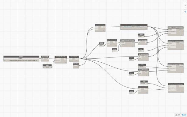
We used Dynamo far more extensively on this project than any that I have worked on before. Normally I’d work with little snippets to process small amounts of data and automate minor repetitive tasks, but this project was a real BIM project; there were no traditional drawing deliverable which actually seemed to genuinely baffle newcomers to the project. The deliverable was the federated model and more importantly the information contained within all the individually modeled elements. A few hours on one of my Sundays and I ended up with what you see below

2016-09-16_14-30-00

That structured mess was able to verify photo file names and associated photo URLs, it verified asset codes were correct and if they weren’t, it generated new asset codes in the required format, it also checked and corrected all the information required to generate those new asset codes and finally probably the simplest part of it all, it filled the project information parameters for us. It was run on all MEP models, with another run on all the architecture models that we created.

Although we were able to automate a lot of really mundane processes, they were for the most part fairly project specific so even though the Dynamo script itself was invaluable to the project, other than the experience provided it doesn’t hold that much value for future projects. There was however one custom node that I put together for the population of Project Information parameters that will probably get used again and again on projects in the future.

2016-09-16_14-48-01

Each input of the node is filled with a string for each individual parameter. In the project, the building name/number parameter relied on the levels within the model being named correctly for which there was another portion of the script that checked that the naming conventions for levels were followed.

The processing of the data itself is performed by Python code inside the custom node, after which the output showed the data that has been filled. You can either pick the custom node up from the MisterMEP Dynamo package or if you want to recreate this yourself the Python code is below

 import clr
clr.AddReference("RevitServices")
import RevitServices
from RevitServices.Persistence import DocumentManager
from RevitServices.Transactions import TransactionManager

doc = DocumentManager.Instance.CurrentDBDocument
projinfo = doc.ProjectInformation
#The inputs to this node will be stored as a list in the IN variables.
OrgName = IN[0]
OrgDesc = IN[1]
BuildNumber = IN[2]
ProjAuthor = IN[3]
ProjDate = IN[4]
ProjStat = IN[5]
ProjClient = IN[6]
ProjAddress = IN[7]
ProjName = IN[8]
ProjNumber = IN[9]

TransactionManager.Instance.EnsureInTransaction(doc)


projinfo.OrganizationName = OrgName
projinfo.OrganizationDescription = OrgDesc
projinfo.BuildingName = BuildNumber
projinfo.Author = ProjAuthor
projinfo.IssueDate = ProjDate
projinfo.Status = ProjStat
projinfo.ClientName = ProjClient
projinfo.Address = ProjAddress
projinfo.Name = ProjName
projinfo.Number = ProjNumber

TransactionManager.Instance.TransactionTaskDone()

elementlist = list()
elementlist.append("DONE!")
elementlist.append(projinfo.OrganizationName)
elementlist.append(projinfo.OrganizationDescription)
elementlist.append(projinfo.BuildingName)
try:
elementlist.append(projinfo.Author)
except:
elementlist.append(list())
elementlist.append(projinfo.IssueDate)
elementlist.append(projinfo.Status)
elementlist.append(projinfo.ClientName)
elementlist.append(projinfo.Address)
elementlist.append(projinfo.Name)
elementlist.append(projinfo.Number)
OUT = elementlist
#OUT = "done" 

Sizing AS3500 Compliant Pipework Using Revit – Part 2

An important part of domestic water design is calculating flow and pressure losses, a common complaint I have from fellow Aussies though is that Revit’s pressure loss report is it’s not in a familiar format and is not something that they’re comfortable including within their design folders. Not to mention, with the AS3500 pipe sizing work(around)flow that I posted last week, the flow rates still don’t quite match up due to the IPC vs AS3500 conversion factor.

So with a powerful tool like Revit at your disposal, why not utilise it to generate data outputs that are in that familiar format and that you are happy to drop into your design notes?

There is always old faithful – the Excel spreadsheet that performs all your calculations..

2016-05-13_17-59-59

..because it’s the way you’ve always done it, so why change right? Not a bad solution if you want to spend the rest of your career manually measuring pipework on drawings to verify your design; ultimately though this is how we came to the true “She’ll be right” Australian method of pipework sizing. After all, doing it properly takes far too long, so just go with your gut and prove your design with actual calculations later, but only if someone questions it down the track.

Did you know you can recreate basic Excel calculations within Revit schedules using calculated values? Of course you did! OK so maybe you didn’t. The problem I have with this method though is due to needing to neutralise Revit units your formulas will start looking a little.. weird.

Take the following example, comparing a simple Excel formula to it’s Revit equivelent

This

=D32*0.001/(0.7854*E32^2*0.001)*1000

Becomes this

=((AS3500_PSD / 1 L/s) * 0.001) / ((0.7854 * Diameter ^ 2 * 0.001) / 1 m²) / 1000

Which how you’d explain that to another engineer I’m not quite sure. They’d probably look at you like you’re a bit odd. So what’s the solution then? Well, maybe you’ve heard of this thing called Dynamo? It’s frequently touted as the best method to model a facade made from old chairs, but did you know that Dynamo can be used for actually useful things too?

In Dynamo, our formula is quite clean and simple, in fact if you squint a little, it looks just like our original Excel formula.

2016-05-13_11-05-15

Armed with that knowledge and a bit of time, that trusty old Excel sheet you’ve been using your whole life can be converted into Dynamo. Once you’ve got the calculations working off your Revit model in Dynamo you can generate all the data within your schedules for every single piece of pipe in your model within seconds. So do you still want to spend the rest of your life measuring pipework? I thought not..

And here are the fruits of my labor. My graph was developed in 0.9, but I can confirm it will work in 1.0 and the 1.0.1 pre-release.

2016-05-13_18-23-13

Stepping through from left to right, this is how it all works:

Starting off simple, I’m selecting all the pipework within the model.

2016-06-15_12-16-57

From there, we’re feeding the All Elements of Category node into the Element.GetParameterValueByName node. Filter out the pipework elements based on their system classification using a combination of String.Contains and List.FilterByBoolMask. This gives a set of true and false results for all of the selected elements, which in this case is our pipework. We take the “in” output of the List.FilterByBoolMask which gives only the elements marked as true.

In this instance I have used String.Contains and checking for the string water. What this means is that it will select anything with water in the name, which would include cold water, hot water, rainwater and so on. You can adjust this to filter out your pipework as you need for as many different systems as needed.

2016-06-15_12-24-58

From this point onward is where all the good stuff happens. We push our pipework out to three separate groups of nodes. A Barrie Smith lookup, velocity calculations and head loss calculations. The Barrie Smith lookup was the most difficult part as it required custom python code to perform the lookup.

2016-06-15_12-32-00

In this group, our results from the previous step feed into the Element.GetParameterValueByName node. We’re picking up the calculated fixture units from our pipework and multiplying it back out by our 3.5x multiplier from my previous post to give us our actual AS3500 compliant fixture units. The code block in the upper left generates a list which is Table 48 from Barrie Smith transcribed to Dynamo. The fixture units and Table 48 are then fed into the custom python node

2016-06-15_12-45-31

The output of the python node then feeds into a math divide node and we divide our flow rate figures by 28.317 and pushes the result to a flow based parameter that I’ve named AS3500_PSD. The reason for division is that Revit stores all units of measurement in imperial rather than metric. When inputting data through Dynamo, Revit doesn’t know that you’re inputting metric figures. What this means is that when you review your data in Revit, you have input 0.23 gallons per minute, not 0.23 litres per second.

Heading back to our second (green) step, the List.FilterByBoolMask node feeds into another Element.GetParameterValueByName node. This time we’re picking up the diameter of our pipework and we’re finding the diameter in imperial and converting it to metric using a formula within a code block.

2016-06-15_12-56-46

The metric diameter from the code block and the probable simultaneous flow rates from the third (blue) step combine first to calculate our velocity. The calculated result is converted back to imperial and populates to a velocity based parameter named AS3500_Velocity

2016-06-15_12-58-48

Our last fork from the second (green) step is to calculate our head loss for our section of pipework. The brighter pink section first takes our length. Now for whatever reason this is taken in millimeters,  so no conversion from imperial required. In the purple section we’re feeding the code block with our pipe size and probably simultaneous flow from previous steps to calculate headloss per 100m, then another code block to calculate headloss for the section of pipe. Finally we push our headloss calculations into their respective parameters AS3500_Headloss and AS3500_HeadlossSection.

2016-06-15_13-09-26

When you’re finished, you end up with a schedule you can drop on your drawing or export to Excel for design verification, and it’s all calculated as you model and far more accurate than you would have ever provided before.

2016-05-12_23-35-53

The example that I’ve used here is highlighting flows where the velocity falls outside the acceptable range of AS3500, so you have a simple visual prompt that you need to check your design. I have found though that most of the time, the design is correct and the sections of pipe highlighted are either 15dia supplying a single fixture with a velocity greater than 3.0m/s or 20dia with two fixtures connected with a velocity of less than 1.0m/s.

Give it a go yourself, once the Dynamo portion is humming along your return of investment is incredibly quick.

Using Dynamo to Generate Mark Parameters from Information in Families

I recently had a question as a follow up to my bi-direction Excel using Dynamo post

Hi Ryan,

I’m trying to use the same concepts to export all structural columns. The node you used (family types) only exports 1 type at the time.

Do you know if there’s a node that lets me export all types of the column family I use in the project?

The node that you want to use to do this is All Elements of Category which you need to feed with your selection from the Categories node.

I thought I would share an example of how I used this node to generate individual type marks for all the columns on the project based off the family name and the level that the column is located on.

Of course generating the mark parameter from the family name means that you need a fairly solid and consistent naming convention in place. You could also use other type parameters within the family, this is just the method that I chose as an example.

Before we get started, I have used the Revit 2015 Sample Structure Project.RVT file and renamed the family types like so


The overview of this particular example of the Dynamo Script looks something like this, so let’s step through what it is doing.

2015-07-13_14-07-01

Getting started, we use our Categories node which we use to select our Structural Columns category. As mentioned earlier we feed that into the All Elements of Category node.

2015-07-13_11-12-25

Stepping through the top row, our elements feed into the Element.GetParameterValueByName node, and we’re picking up the Base Level parameter.

2015-07-13_13-49-43

2015-07-13_13-51-31

We then pass through to the Level.Name parameter which gives us the level name as you see it in the project browser as a string, which in this case is “01 – Entry Level”. Using the String.Split node we split the string in half using a Code Block node and entering ” “; into the code block to denote the space.

Think of this as the same as the Text to Columns command in Excel.

This gives us a list that splits the level name into

“01” “-” “Entry” “Level”

From here, run the data through the List.Transpose node and then finally into the List.GetItemAtIndex node, here we need the row at line 0 so we use a Number node to define the index.

You can alternatively use a Code Block node and enter “0”; as the code which works the same as the Number node.

On the bottom row we are taking our family type name and pulling out the type itself from the string that is returned. Even though when scheduling the Type parameter returns just the type, the string that is actually returned from Dynamo is in the format of Family Type: CRC 450, Family Name: STR_CONCRETE_ROUND_COLUMN.

So following a similar sequence to the top row, we split the string down to what we want which is “CRC 450”, to do this we need to split the string twice; first by the colon ( : ) and then by the comma ( , ). As you can see in the screenshot we need to transpose the list and pull the data at each row twice to get what we’re after.

2015-07-13_14-20-45

At the lower right corner there is a number generator. It is simply stepping from 1 to 200 in increments of one. Make sure to run the Number.Sequence node through the List.Transpose otherwise you will cause Dynamo to lock up while generating incredibly long number strings if you feed the sequence directly into the mark parameter.


Finally, we use a Code.Block node to concatenate the data we have pulled into a single string. The code block is simply a+b+c+d; which gives as four variables of the same name that we can feed the rest of our data into.

I have then created another list which consists of the Element ID and the string, we then finish up by selecting our string and populating the mark parameter as per my bi-directional Excel post.

Of course there are other options where you can generate the mark parameter from other type parameters in the family, I just chose to use the type name as the example this time around as I could show how you could break down a long string and the data you need from it.

Taking a Return Trip From Revit to Excel Using Dynamo

Last week I wrote about using note block schedules to create specification sheets and I explained how you can use addins such as BIMLink, custom macros or C# addins or Dynamo to get the data out to Excel so that it can be edited by an engineer and then re-imported to Revit from Excel.

Problem is, you don’t have a BIMLink licence, you don’t know how to code in C#, the most accessible method for you to achieve this workflow is Dynamo but you don’t even know where to start; never fear! In this post I explain how to create a bi-directional link between Revit and Excel using Dynamo using the as the note blocks from my previous post as an example.

I’ll be using Dynamo 0.80 which can be found on the Dynamo BIM download page.

Exporting from Revit to Excel

The export to Excel process is pretty simple, you just need to think about the logical steps that you need to take. You want to select the family you wish to export data from, select the parameters to export, organise them in a list and then write it to the Excel file itself.

To step through the process, first select the family type and push that into an All Elements of Family Type node.

2015-06-11_12-33-39


From there we start our first step in taking care of the family unique identifier by using the Element.UniqueId node, this will export the family’s GUID. Simply link the All Elements of Family Type node to this one. You need to export each individual family’s unique identifier as well, if you don’t, as the BIM Troublemaker discovered you may end up importing the wrong data to the wrong family.

Next, you need to select each of the parameters you want to export, for this you need to use the Element.GetParameterValueByName node. Link the All Elements of Family Type node through to this node and you will also need to add a String node which is where you input the name of the parameter. Because I’m using the annotation family from my note block post, the parameters that I will be exporting are NUMBER, NOTE, CATEGORY and REGION. Note that the value that you enter into the string is case sensitive and that you need to repeat this for each parameter you are wanting to export.

2015-06-11_12-33-50

Now you need to push the output of each of our Element.GetParameterValueByName nodes through to the List.Create node. This will actually create a list that will run the parameters across the page with each parameter being spread across a row instead of being arranged in columns. If you exported the data to Excel at this point, you would end up with something that looks like this:

2015-06-11_12-46-17


However this isn’t how we want to work, we like our data arranged in columns. To do this, use the List.Transpose node which swaps the rows and columns in the created list.


To finish off we need to use the Excel.WriteToFile node in which we pass through a File Path node, a String which names the Excel sheet and a few Numbers which gives the starting row and column of our excel sheet.

The result is a nice, easy to read export of all the data relevant to our note block schedules ready to be modified by an engineer.

2015-06-11_12-56-52


At this point you can use the Sort function in Excel to sort your Excel file into a usable list. In this instance I have chosen to sort by Column D and then Column B so that I am sorting first by category and then by note number.

2015-06-11_14-18-21

Importing back into Revit from Excel

Once the engineer has finished modifying the Excel sheet, we’re ready to bring the data back into Revit from Excel. This process is slightly more cumbersome but overall not a whole lot more difficult than the export process.

2015-06-11_13-24-16

First we need to pick up our Excel file, start with the File Path node that we used before, before we go to the Excel.ReadFromFile node though we need to pass the file path through the File.FromPath node otherwise it will not work. We also need to add a String so we can tell Dynamo which sheet to read. Next, pass the data back through the List.Transpose node to get the data back into a format that Dynamo and Revit are happy to work with.

2015-06-11_13-27-55


Remember earlier I mentioned during the export process that to make sure we’re writing the correct information to the correct family we need to index our list and the families by their GUID? Thanks to the BIM Troublemaker, we know how to select each element from our Excel file based on the GUID. First, start with a List.GetItemAtIndex node and connect the List.Transpose node to it. Next, add a Code Block node and enter the text 0; this passes through the number 0 as our row index. Finally, add a Code Block node and insert the code  ElementSelector.ByUniqueId(id, true); this is case sensitive, so make sure that you enter it correctly or it will not work!

2015-06-11_13-35-13


Finally, we need to push the data through to each parameter for each individual family. To do this, use an Element.SetParameterByName node. We need to feed the ElementSelector Code Block that we created into our node, along with a String node that matches our parameter name, remember this value is case sensitive and finally we need to link up our value via a List.GetItemAtIndex node.

The List.GetItemAtIndex node needs to be told which row to use to pull it’s data from, this is as simple as adding a Number node. Don’t forget though that the first row is at index 0, which is where we are pulling our GUID from, so we want to pull our first series of parameters from the row which is at index 1.

In this instance our index 1 is our number list which you may not need to import this so you could skip this step, but if you do need to populate the number data and you try to feed the parameter from the List.GetItemAtIndex node directly to the Element.SetParameterByName node Revit will throw back an error stating that “The parameter storage type is not a number”. Originally I tried to overcome this by using the node String from Object but this gives a number to 3 decimal places and we don’t want to see this on our specification sheet. The solution in this instance was to first use the Math.RoundDownToPrecision node from the Clockwork package which you can download from within Dynamo itself or from dynamopackages.com. We need to pass a number to the Math.RoundDownToPrecision node to indicate the precision we want, which in this case we want a precision of 1.

The number conversion is the only oddball of the parameters that we’re working with, the rest of the parameters simlpy feed the List.GetItemAtIndex node directly to the Element.SetParameterByName node. Repeat for each parameter that you want to populate.

2015-06-11_13-44-43


And to finish up, our results: