
I’m going to quickly run through the steps of creating an Allproof Boss Gully which you can find at Allproof’s site here: http://www.allproof.co.nz/boss-gully-trap
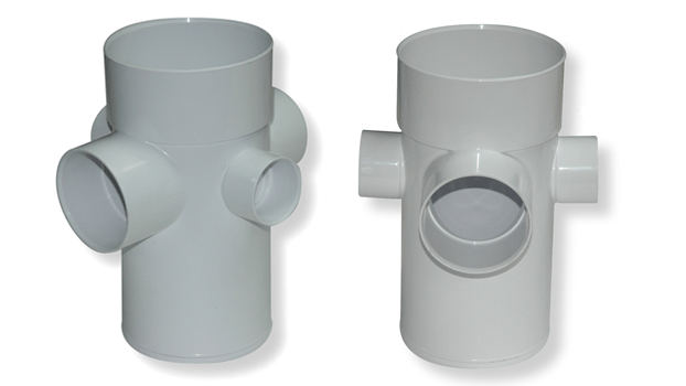
The Boss Gully is a problem solving product for when there is limited available ceiling space to run drainage. The total depth of the Boss Gully is 219mm compared to the standard depth of 250mm. 30mm might not seem like much of a difference, but sometimes you need all the extra space you can get.
After creating and re-creating standard 100mm and 80x65mm floor waste gullies in the past, I have learnt that the best starting point is a non-hosted family template. Previously I had created gullies attached to a face (as you can not attach to a floor of a linked model) however problems arise in the instance that the architect changes a room location by a significant amount, a floor level height or completely deleting and re-creating the room/floor, moving the gully with the attached floor and disconnecting pipework and generally causing headaches. The other advantage of a non-hosted floor waste gully is that a level of complexity is removed as parametric data for the depth below the slab and slab thickness is no longer required to locate the gully in the correct space.
I am creating this family in Revit MEP 2011 as I like to keep families compatible with at least one previous release in case the project architect has not upgraded to the latest Revit Architecture.
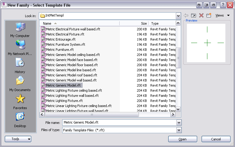
- Select ‘Metric Generic Model.rft’ from the family template files

- Create reference any reference planes required. In this family, I placed reference planes as I built the model.

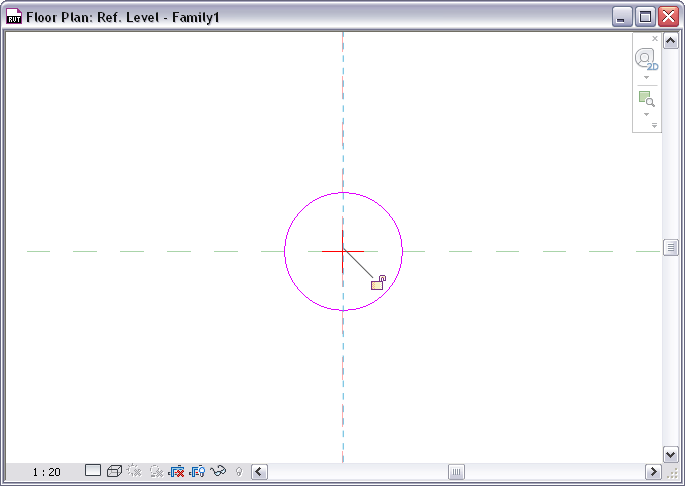
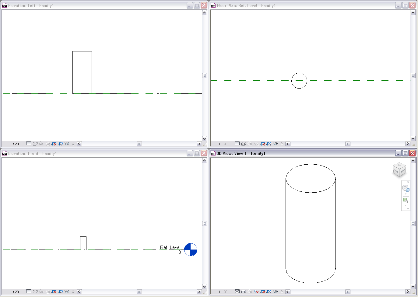
- Create a cylindrical (circular) extrusion in the reference level view. This will be our floor level.

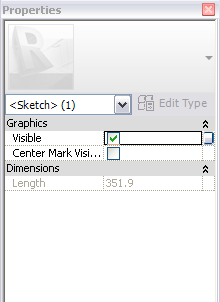
- In the extrusion editor, select the extrusion you have just created (pink circle) and in the properties window, tick the ‘Centre Mark Visible’ check box.

- Align and lock the extrusion to the reference planes

- Repeat the above steps to create another extrusion for the larger top section of the gully.
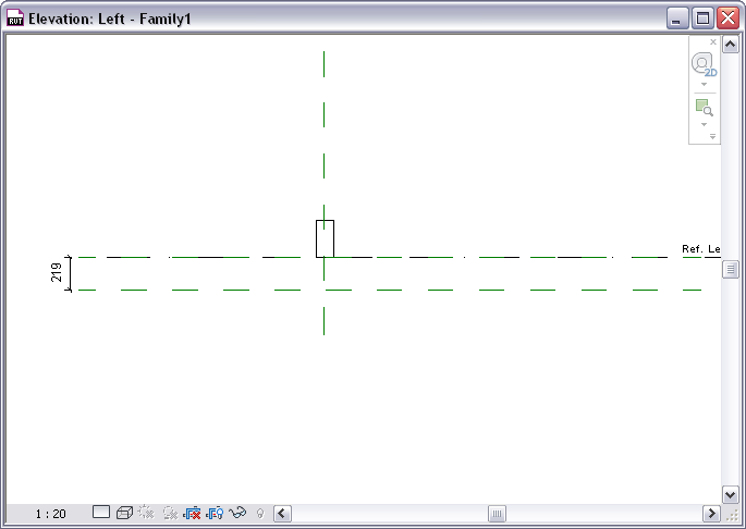
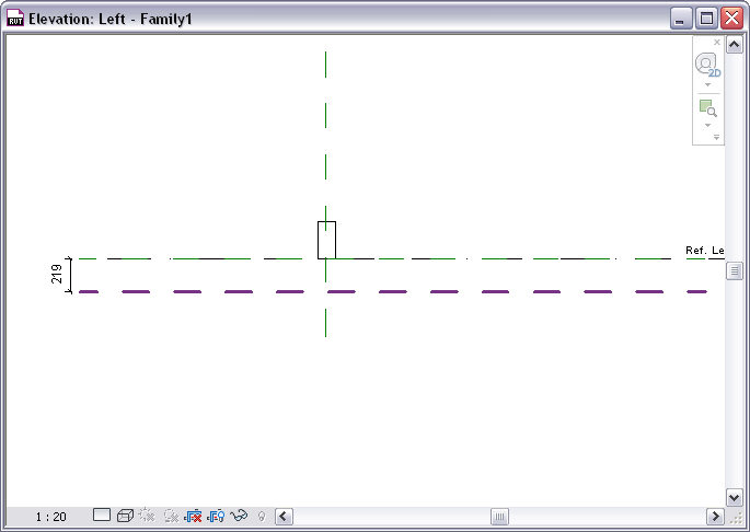
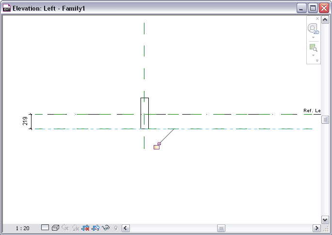
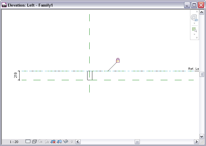
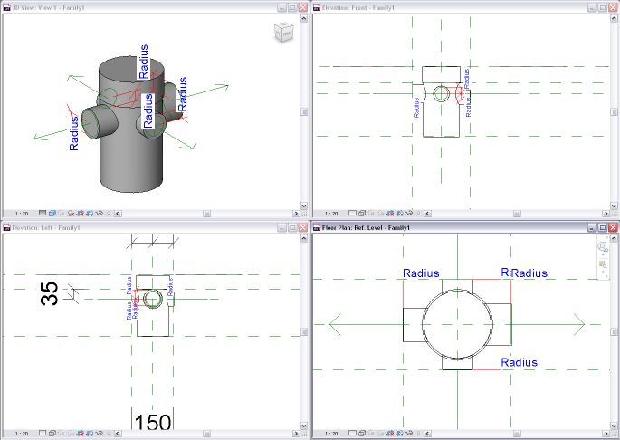
- Use the Aligned Dimension (DI) tool to dimension the reference planes in the front view. Set the depth of the reference line from the reference level to 219mm. Add another reference line at the dimensioned and locked to the point the gully changes diameter. Align and lock the extrusions to each reference plane as required.


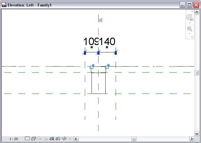
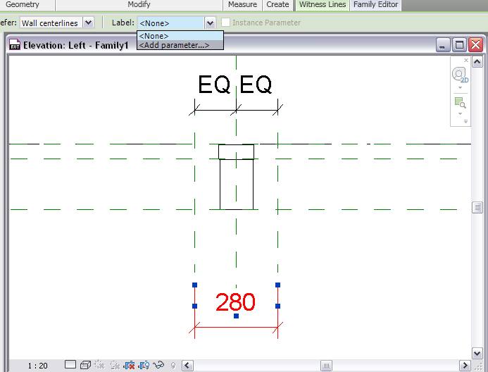
- In the front view of the family, create reference places to lock the outlets to. This is more useful when adding parameters if the overall gully diameter is going to change with multiple family types. Once the reference planes have been created, add Aligned Dimensions (DI) across the top, make the dimensions equal using the ‘EQ’ button, then dimension the reference planes once across the base dimensioning to the correct width.
 It is a good idea to keep your dimensioning consistent within your families. My personal preference is all ‘EQ’ dimensioning to be located at the top and left of the family and to locate all other dimensions (fixed or parametric) to the right and bottom of the family. This helps to keep things neat and somewhat clear when creating more complex families involving many dimensions.

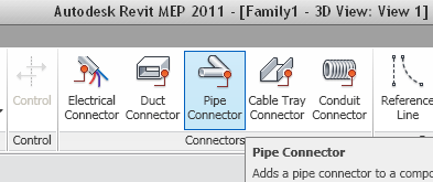
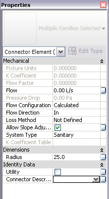
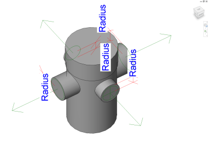
- In the 3D view, add pipe connectors, remember to set each connector as the correct system type and flow direction. It is also important for drainage connections to make sure that the ‘Allow Slope Adjustment’ check box has been ticked.


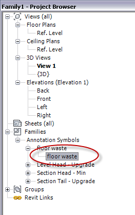
- Next we will add the 2D symbol for the gully. Insert your annotation symbol into the reference level using the centre reference planes as the insertion point.


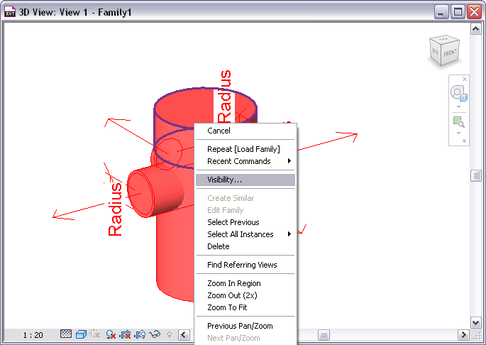
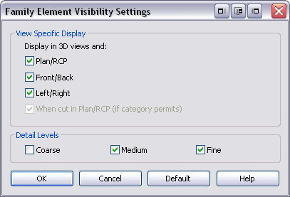
- The next step is to set the required visibility settings. I tend to only differentiate between coarse and fine views, showing only 2D symbols in coarse view and the 3D elements in fine view. You can however set the visibility as you require.


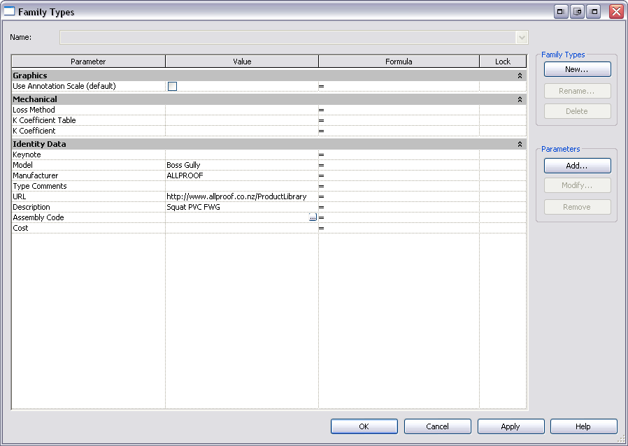
- Add all the required Identity Data to your family. Manufacturer, model, URL and any other as required such as ‘family created by’ and ‘family checked by’

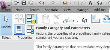
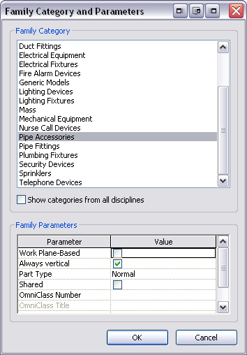
- Finally, don’t forget to set the family category correctly. Most plumbing families such as this floor waste will be a pipe accessory. If you have ever experienced a family being greyed out once it has been inserted, or not appearing in your view at all, it is usually because the family category has not been correctly set – usually still set to ‘generic model’.


- The Boss Gully is now complete. Save your family and start using it in your project.




[iframe: src=”http://freewheel.autodesk.com/dwf.aspx?path=http://www.revit.com.au/dwf/allproof_boss_gully.dwfx&sec=1&px=-0.36762658&py=-0.051401582&pz=0.61487916&tx=-0.028872337&ty=-0.35677867&tz=-0.029157214&ux=0.25338510&uy=0.91887885&uz=-0.30241968&fx=0.046280050&fy=0.88976655&proj=orth&q=high” frameborder=”0″ width=”100%” height=”600″ scrolling=”no”]
One thought on “Family guide – Allproof Boss Gully”