Ryan Lenihan

Building Healthy Asset Models

Understanding how to integrate with your client’s asset and facility management requirements at first seems like a daunting task, however getting it right can be as simple as asking the right questions.

From the perspective of a project manager or even an asset owner, some of the questions that should be asked are:

  • When will the facilities management team get access to the model? Will it be during the design phases of the project, or will it be once the design is complete?
  • Will the facilities management ream be able to dictate to the design team what information is incorporated in the model?
  • Will the facilities team be able to review the model before construction and commissioning?
  • Will the facilities management team own the model when it is completed?
  • Who maintains the model once handover is completed?

Then there are questions that the more technically minded team members tend to focus on around information requirements

  • What information does the facilities team require?
  • Do the facilities team actually need all of this information?
  • What data formats does the facilities team require?
  • Do they have existing non-BIM facilities packages that require integration into the new BIM enabled system? Can it be integrated at all?

If you’re interested in how I approached the problem of recording existing assets in one of Australia’s largest health precincts, take some time out to check out my AU2018 presentation

https://www.autodesk.com/autodesk-university/class/Building-Healthy-Asset-Models-Case-Study-Existing-Asset-Recording-BIM-2018

With a special guest appearance about halfway through from probably Autodesk University’s most famous cat, Burrito. One of the dangers of presenting remotely.

Don’t Have Dimensions in Families for COBie? Don’t Worry!

So you’re new to COBie and a deadline is approaching, your favourite project BIM manager comes up to you a few hours before the deadline and tells you “We have to do dimensions.. on every element in the COBie drop. You have your dimensions ready right?”

Well there is no need to stress, as always there is potential for Dynamo to come to the rescue. I put this one together in Dynamo v1.3, but I have tested it in v2.x as well and it still works just fine, just a note though. If you save your old 1.3 graphs in 2.x, it’s now a 2.x graph forever.

The way that I approach the majority of my COBie work is through a 3D view and a schedule with a set of very hand filters, so I’ve continued down this route for my Dynamo graph and I start it off by getting all the elements in the active view – my 3D COBie view.

Just in case there is anything in the view that isn’t a family I’m getting the element type of each element, convert that value to a string and then filter the list based on the string “family”. This is because every family in the view will be prefixed with Family Type: whereas non-family objects will not.

Once we have the filtered list of families, we need to take the bounding box of each element, we do this with an Element.BoundingBox node. Using Spring Nodes, we next use Springs.Geometry.Extents to separate out each dimension individually.

The next step is a bit of simple math. I want to ensure that the length parameter is always longer than the width, so with a few if statements and some greater than and less than nodes, the top pair of nodes always provide the smaller number that will populate our width parameter and the lower set of nodes now provide the large number which will feed into our length.

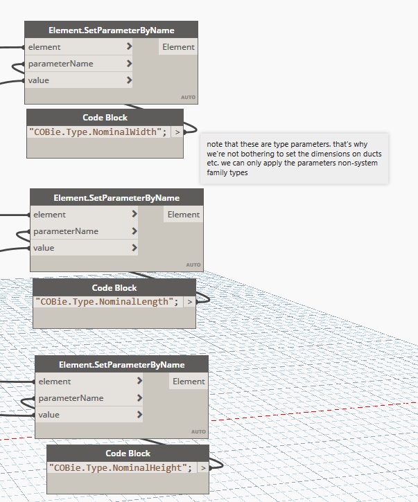
Finally, we populate our parameters with the correct information. Note that your parameters must be set correctly to type parameters for this to work, if you have incorrectly made them instance parameters the script will not work but if you’re paying attention you’ll see that the hint is in the name of the parameter.

Now, don’t forget that with the COBie element data, you should be nominating dimensions inclusive of the maintenance requirements for that object, you could always add a little bit of extra fat to your dimensions, but I would highly recommend approaching COBie and BIM in general the right way and including spatial elements that indicate the overall dimensions including maintenance access similar to what is shown in the electrical switchboard below.


For those that want to get stared a bit quicker, I’ve provided my graph for download below

Using Dynamo to Insert a DWG Into a Revit Family

Another question that I’d rather not have the answer left to email

I have a project on which HVAC is using AutoCAD MEP for their ductwork (they don’t know Revit…yet). They’re designing in 3D based off my Revit-to-dwg exports. But the only way I can import their 3D ductwork from AutoCAD MEP into Revit, AND have it respect my cut planes in my sheet views, is to bring it into a Revit Generic Family first.

..snip..

Any ideas on how to improve this workflow (aside from making HVAC work in Revit)? Maybe some sort of Dynamo script to help automate this process?

This is a workflow that I’ve only had to follow a few times when working with a bridge team that was still working in AutoCAD. I guess I’ve had the luxury entire project teams working in either Revit or ArchiCAD and working with this files is a straight forward process.

There is a Dynamo solution that works well, but my first iteration of this doesn’t automatically batch process all the files, but rather it’s run on an as-needed basis. This isn’t such a bad thing though as every DWG file usually isn’t issued all at the same time.

My Dynamo solution requires that you have

  • Dynamo 2.x
  • GeniusLoci package
  • Excel list of  families and their corresponding DWG files

First we start off with reading our Excel file, it provides the validation between our RFA names and the required DWG to be inserted to that RFA. I have a dummy list of files, but it shows how the concept works.

Our Excel file has headers included, so we split our our headers with a List.Deconstruct node and we transpose that list so we split out to a list of RFA files and a list of DWG files. Then using a List.GetItemAtIndex node we take the name of the RFA file from the list to validate that against our open document.

Next, we take the name of our open document. Sometimes this node won’t refresh to pick up the current document name, if this is the case, just close and re-open the graph.

The nodes are reporting back not just the file name, but the location that it is saved. To be able to break the string down into it’s separate pieces, we use a String.Split node and split by the string “\\”, once we’ve split the string the split elements will be provided in a list. We simply want to take the last list item as that will be our file name.

Now that we have our file name from our current document as well as the file names from our Excel list, we want to use a List.IndexOf to search our Excel list for the name of our currently open document (final node in the above screenshot)

From there, we can take the list of DWG files from our Excel sheet and using the value produced from our List.IndexOf node we can pull the corresponding DWG name from our Excel list.

We then need to put together a path string. You could hard code this into the code block or you can use the Directory Path node to feed into the code block.

Next is the bulk of the work, with the help of the GeniusLoci package we need to enumerate the DWG import settings available to us. We then take those lists of settings and using a List.GetItemAtIndex node we select our import settings to then feed into our Python script.


The Python script is a modification of the existing Import DWG node from the GeniusLoci package, we just need to change a single word within the script as although the existing node is called Import DWG it actually links the DWG files.

So on line 60 of the script we need to change doc.Link

doc.Link(filePaths[view], options, views[view], linkedElem)

to doc.Import

doc.Import(filePaths[view], options, views[view], linkedElem)

Rather than modify the GeniusLoci node itself, I have created a new Python script node and put the modified code within that node.

Complete Import DWG Python Code
[python] # By Konrad Sobon
# By Joseph_Peel
#By Alban de Chasteigner
import clr
clr.AddReference(‘ProtoGeometry’)
from Autodesk.DesignScript.Geometry import *

# Import DocumentManager and TransactionManager
clr.AddReference(‘RevitServices’)
import RevitServices
from RevitServices.Persistence import DocumentManager
from RevitServices.Transactions import TransactionManager

doc = DocumentManager.Instance.CurrentDBDocument
uiapp = DocumentManager.Instance.CurrentUIApplication
app = uiapp.Application

# Import RevitAPI
clr.AddReference(‘RevitAPI’)
import Autodesk
from Autodesk.Revit.DB import *

#The inputs to this node will be stored as a list in the IN variables.
dataEnteringNode = IN

filePaths = IN[0]

if not hasattr(filePaths, ‘__iter__’):
filePaths = [filePaths]

views = UnwrapElement(IN[1])

if not hasattr(views, ‘__iter__’):
views = [views]

customscale = IN[2] colormode = IN[3] placement = IN[4] unit = IN[5] viewsplaced = [] outName = [] CADlinktype = [] importinst = []

options = DWGImportOptions()
options.AutoCorrectAlmostVHLines = True
options.OrientToView = True
options.ThisViewOnly = True
options.VisibleLayersOnly = True
options.CustomScale = customscale
options.ColorMode = colormode
options.Placement= placement
options.Unit = unit

linkedElem = clr.Reference[ElementId]()

for view in range(len(views)):
TransactionManager.Instance.EnsureInTransaction(doc)
#doc.Link(filePaths[view], options, views[view], linkedElem)
doc.Import(filePaths[view], options, views[view], linkedElem)
TransactionManager.Instance.TransactionTaskDone()
viewsplaced.append(views[view])

ImportInstances = FilteredElementCollector(doc).OfClass(ImportInstance).ToElements()

for importinstance in ImportInstances :
if importinstance.IsLinked:
importinst.append(importinstance)
for importins in importinst :
CADLink = doc.GetElement(importins.GetTypeId())
CADlinktype.append(CADLink)
name = Element.Name.GetValue(CADLink)
outName.append(name)

#Assign your output to the OUT variable.
OUT = viewsplaced,outName,CADlinktype,importinst
[/python]


And that is it. Once all the required data is fed into the Python script, the DWG is placed on the view and our job is done.


If you have a need to import DWGs into family files and want to get started a bit quicker, you can download my Dynamo graph below

Merging IFC Files with BIMServer

A question came through via email the other day in the office

We’ve been trying to issue federated IFC files, but the combined size balloons up to 20x the original size. Is getting these models to a consumable size a wild goose chase?

Well, the short answer is no, it’s not a wild goose chase and it is possible to generate federated IFC files that are almost exactly the same file size as the sum of the smaller files.

The long answer?

Open up this page in a browser:

https://github.com/opensourceBIM/BIMserver/releases/tag/1.4.0-FINAL-2015-11-04

Download 1.4.0-FINAL-2015-11-04.jar, save it somewhere on your local machine. Don’t use spaces in the folder names when you save it or the tool won’t work properly, use underscores if you need a space.

There is even quite a comprehensive help document with information on configuring the BIMServer tool:

https://github.com/opensourceBIM/BIMserver/wiki/JAR-Starter

There is not a lot to do in the setup process though, I just made sure I was set to local host and that there were no conflicts with my port and then clicked start. After you click start, it will take a while to run through what it needs to do, when finished you’ll see a line that looks like:

02-10-2018 11:23:33 INFO  org.bimserver.JarBimServer – Server started successfully

Now click the launch web browser button. It will take you to a window that looks like this:

For all the work that you are going to do from here on, you need to use Chrome or similar. Internet Explorer will not work. Also note that if you log yourself out, you will need to log back in with your email address as the username, not your name.

Fill out this page with your details, you’re creating a user here. You will be able to login with these details again in the future. Because this is a web application, we could actually host this internally and have a permanent server setup, it’s just this workflow is using it as a web application hosted on your local machine.

Now that you have created your user and logged in, you will now be in a project browser. Select Project -> New Project

Fill out the details as required to create your project:

This provides essentially a bucket that you store all of your data. The next step is to create sub-projects to add your IFC files that you want to merge

To then upload a model to each sub-project, you need to use the “Checkin” option. It will take a little while to import the files depending on how complex they are.

My files are between 30 – 70mb each depending on the file. They take about 4-6mins to import using a laptop with an i7 6820 CPU

You’ll know that the files are importing because the IfcGeomServer will be using CPU:

You can view your model in the web browser to verify everything is in the correct location by clicking on the eye (grey = off, coloured = on)

For the merge, you literally just have to click the little arrow to the right of the top level project, and select download.

Depending on how big your models are, the problem might be if you have enough memory to perform the merge.

If the download doesn’t work, hit the back button or refresh the main page before you try and download. You need to see an eye on the top level project for the download to work.

You can verify your IFC file either by loading it into a new project within the BIM Server web application, or you can load it into Navisworks.

My resulting IFC file is 173mb which is exactly the sum of my four individual files.

If you want to try reduce the size of the IFC file, use the Solibri IFC Optimiser

https://www.solibri.com/solibri-ifc-optimizer

After running the optimiser, the file size was reduced to 124mb.


Calculating and Tagging Pipe Obverts with Dynamo

There are times when we need to show a little more information than Revit is able to provide out of the box. Take for example internal pipe inverts and obverts. When tagging pipework, you can tag the quadrants of the pipe and the centre node.


So what do you do when you need to tag the the internal features of the pipe? The best method is to create parameters that can be filled out automatically using Dynamo. The central start and end node is already recorded in each piece of pipe, we just need to adjust those figures by the internal diameter and populate some parameters with that information. We would realistically need to add four new parameters to our piping:

  • Upstream Invert
  • Downstream Invert
  • Upstream Obvert
  • Downstream Obvert

These parameters will need to be Shared Parameters so that you can tag them later. In my example I have set the parameters up as number parameters, they are associated with the pipe category and they are instance parameters.

Once you have the parameters setup, start up Dynamo. For reference I’m using 1.3.3, but you could also use Dynamo 2.x.

The first step is collecting the information required to generate the correct inverts an obverts. For this we need the start and end offsets as well as the internal diameter.

The next step is to calculate the inverts and obverts. This is as simple as taking half of the internal diameter and then adding to the starting and end offsets for the obverts and then subtract the values from the start and end offsets for the inverts.


Finally we need to push these calculated values back to the piping. There is a small check required to ensure we input the correct data to the correct parameter, the reason being that the start and end offsets don’t relate to the upstream or downstream end of the pipe, but rather the start and end of the direction the pipe was drawn from.

The check is a simple if node, which checks which value is greater and places the larger of the values in the upObvert and the downObvert parameters.


The final step in the process is to create a pipe tag with labels for each of the relevant parameters and viola!


I have made all the files used in this demonstration available for download

Step by Step Guide – Creating My Iplex FWG Family in Revit

A lot of people ask me if I’ll give them my Iplex floor waste gully family. The answer is always no, not because I don’t want to share, but because I would rather people learn and understand for themselves rather than taking the easy way of “grabbing something from the internet”

I recorded a video on how to create the FWG a long time ago, but after a bit of back and forth discussion on Youtube, I have decided to pull that old video out and record some voice annotation so you can follow along.

I do apologise about the audio quality, I only had my junky work headset to record with.


Yes, this is how I spend my nights in hotels when travelling for work.

Fixing SP.Writer Run Time Error 70

If you’re like me, you haven’t used SP.Writer in a while but then if you’re also like me, you will at some point need to use it to generate a project customised shared parameters file. The first thing you do is pull out your trusty SP.Writer only to find that when you create a new parameter you get a run-time error 70.

If you hit the debug button, you will be taken to the mod_GUID module and the 4th line will be highlighted as the problem child.

The function used to create the GUID in SP.Writer was patched in the July 2017 security patches for Microsoft Office so if you’re up to date with your security patches, this is working as intended. That doesn’t help us in the slightest with creating shared parameters though, so what’s the solution?

First if you haven’t already done so, you’ll need to enable the developer toolbar in Excel which you can do by following the instructions over at the Microsoft website.

Once enabled, select Visual Basic from the developer tab on the ribbon. Alternatively you can use the ALT+F11 shortcut on your keyboard.

On the left hand side of your screen, you will see a window titled Project – VBA Project, scroll down until you find Modules. Right click on modules and from the contextual menu select Insert.. -> Module.

Copy and paste the following code into the new module.

Private Type GUID_TYPE
Data1 As Long
Data2 As Integer
Data3 As Integer
Data4(7) As Byte
End Type

Private Declare PtrSafe Function CoCreateGuid Lib "ole32.dll" (guid As GUID_TYPE) As LongPtr
Private Declare PtrSafe Function StringFromGUID2 Lib "ole32.dll" (guid As GUID_TYPE, ByVal lpsGUID As LongPtr, ByVal cbMax As Long) As LongPtr

Function CreateGuidString()
Dim guid As GUID_TYPE
Dim sGUID As String
Dim retValue As LongPtr
Const guidLength As Long = 39 'registry GUID format with null terminator {xxxxxxxx-xxxx-xxxx-xxxx-xxxxxxxxxxxx}
retValue = CoCreateGuid(guid)
If retValue = 0 Then
sGUID = String$(guidLength, vbNullChar)
retValue = StringFromGUID2(guid, StrPtr(sGUID), guidLength)
If retValue = guidLength Then
CreateGuidString = sGUID
End If
End If
End Function

You can also rename the module, I renamed mine to mod_CoCreateGUID as this is will be method we’re using to generate the GUID. If you can’t see your properties window, press the F4 button.


Next, open the module mod_GUID and replace the existing code with the code below


Sub GetGUID()
Dim sGUID As String
sGUID = CreateGuidString()
wsData.Cells(LastRow + 1, 2) = "PARAM"
wsData.Cells(LastRow, 3) = Replace(Replace(sGUID, "{", ""), "}", "")

End Sub


The final step is to make a small change to the UserParameter form. In the VBA project, find the UserParameter form and right click and select View Code from the contextual menu.

Search for the code


'generate the GUID
GUID

and replace with the code


'generate the GUID
GetGUID

and that’s it! You’re done! You can now start creating shared parameters again. The GUID looks a little longer but it’s actually just the difference in length between upper and lower case with the font used.

C4R – I’m Still Missing Too Many Elements! (Part 2)

So last week you went through how to fix the ‘too many missing elements’ error, but after clearing your cache and sourcing replacement files you’re still seeing the error.

This means things are a little more serious, but there is still a potential solution.

Search the Journal for Missing Element Warnings

This time around, you need to review the journal file and look for the error specifically related to missing elements.

The journal file is located in %LOCALAPPDATA%\Autodesk\Revit\Autodesk Revit 201x\Journals you need to be opening the journal file that will have recorded the error. If there error has just occured, it will be recorded in your most recent journal file.

The easiest way to find the most recent file is to change your file sorting by date modified with the newest files at the top.

Open the journal in a text editor (Notepad or Notepad++) and search for the name of the model causing the problem.

This time you want to search for the text missing elem within your journal file.

If you can’t find the text in your most recent journal file, don’t panic! Using Notepad++ you can actually search for a string in all files located in a folder.

The search results will appear at the bottom of Notepad++ showing which files it has found the search string in.

You will soon have a list of elements that are missing from your model. The numbers represent the element ID of the missing elements.

Repairing the damage

To recover your file, locate the most recent backup file that contains the missing elements. You can restore backups from your local cache in the same way you have always been able to restore backups with Revit, it’s just now there is an extra step in finding the GUID of the RVT file before you can restore a backup.

Search for the name of your Revit file in the journal. This will give you the GUID for the project and file.

Once you have found the name of the model,take the model GUID and search for it in your CollaborationCache folder. You need to find the folder named <revit model GUID>_backup

From the Collaborate tab of the ribbon, select Restore Backup

Paste your backup folder path into the folder name location, it should follow the format C:\Users\<user name>\AppData\Local\Autodesk\Revit\Autodesk Revit 201x\CollaborationCache\<local cache id>\<project GUID>\<model GUID>_backup

Select the most recent backup and work your way back until you find a working copy.

Save the file in a new location. Don’t open the file just yet.

Browse to where you have saved your backup file and then open the file with the audit box checked.

Once you have successfully opened the model, using the Select by ID tool, search for the elements in your backup model.

Make sure that all the elements display correctly and work as expected.

The audited model becomes your new central model. You need to run through the process of loading the model onto C4R.

If anyone else is working on the project, their local cache will no longer synchronise with the newly created cloud model. Others in the team will need to rename or delete the folders in both their CollaborationCache and PacCache folders.

And that’s it! You’re done!

One final note..

When speaking with Autodesk, they advised that the best way to prevent this missing elements error is to always open your C4R models with the audit check box ticked. It’s a little bit of extra pain, but if it saves you from having to manually recover models, then happy days!

Final note for real this time..

In addition to the above, both Revit 2017 and 2018 have had updates released since I originally wrote this post. Autodesk’s urge anyone that is experiencing too many missing element errors to update their entire team to Revit 2017.2.2 and/or 2018.1.1. The patches for both fix the problems that cause these errors.

Aligning 3D Section Boxes

A quick one that came up today.. “Ryan, how do I align a 3D section box with an object that is not at right angles to the view?”

So what we’re talking about here is when we have a plan view that is rotated away from a straight up and down orientation.


When you create your default 3D view, it might end up looking something like this. You can rotate the section view but it’s a “near enough is good enough” approach and you can never truly align your section box.


That is unless you think about things a little differently. I’ve been preaching this method for quite a few years now but it seems be be a tool within Revit that not a lot of people know about.

Simply draw a 2D section that aligns with your building. If you need, you can draw detail lines to help in aligning your section, but Revit should automatically align with elements such as grids and walls in your model.


In your 3D view, right click on the view cube and then select Orient to View -> Section -> Section xx

And that’s it! You’re done!