Ryan Lenihan

Keeping Reference Tags Under Control

One of my pet hates when helping people out with their models are view tags. More specifically, when they are all turned off. Usually they don’t want the unreferenced view tags to print, so they just turn off the whole lot rather than go about it in a slightly smarter way.

My first recommendation would be to check your print settings and check the box that says “Do not print unreferenced view tags”

 This however only hides the view tags when printing. Your view will still be quite busy with markers and tags littering your screen.

What happens if you want to maintain a ‘working set’ and a ‘plot set’ of views? Leaving all markers visible in the working set and only the referenced markers visible in the plot set?


There is a much more elegant solution that you could implement using filters.


Firstly, load the visibility/graphics window (vv or vg), switch to the Filters tab and select Edit/New..


In the filters dialogue box, first create a new filter, name the filter ‘Unreferenced View Tags’


From the categories column, select Callouts, Elevations and Sections.

From the ‘Filter by‘ drop down, select ‘Sheet Number‘ and ‘Contains’


Because I work in hydraulics, I have placed a H in the filter as all my drawing numbers include the letter H

For unreferenced view tags, you would select the filters as ‘Does not contain’ and you can leave the filter blank.


Back in the filters portion of visibility/graphics overrides, select ‘Add/New..’ and select the view filters you have just created


In the filters tab of visibility/graphics overrides, you simply need to check or uncheck the box as required.

Preparing Architectural Models for Linking – Deep Purge


If you’re having trouble with computer performance on large Revit projects, before trying to have new computer purchases approved, first try to clean up the incoming architectural models.

Simple as Manage Tab -> Purge Unused right? Wrong.

All the views, sheets, schedules and legends within a Revit model consume valuable space, which in turn increase load times, memory usage and processing power. This of course equates to reduction of overall performance and reduced efficiency of the modelling team.

The steps that need to be taken are:

  1. Open the architectural model, detaching it from central
  2. Remove all links. Revit, CAD and otherwise
  3. From the View tab, select Revisions and uncheck all items in the ‘issued’ column
  4. Delete all the unrequired views. Keep any views that you need to link into your model.
  5. Delete all schedules and legends
  6. From the Manage tab, select Purge unused. You may find that you need to purge 2-3 times before all unused items are purged.
  7. Save the files and compact the file on saving

It will depend on just how much you were able to remove as to how far the file size will be reduced, but it is not unreasonable to expect reductions of nearly 50%

It is possible to save time on step 4 by changing the sorting method of the Project Browser, depending on how the architects have structured their Project Browser.

Revit MEP 2012 – Parallel Pipes Disappear

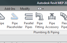
Have you gone to use your parallel pipes tool, but the button has gone missing from the ribbon?

There is a bug in Revit 2012 which causes both the parallel pipes and parallel conduit tools to disappear from time to time.

The quick and simple solution is to use the hot keys PE for parallel pipes or PO for parallel conduits.

Once you have run the tool from the hot key, the button will also re-appear on your toolbar.

Selecting pipes but can not select fittings

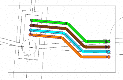
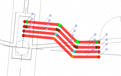
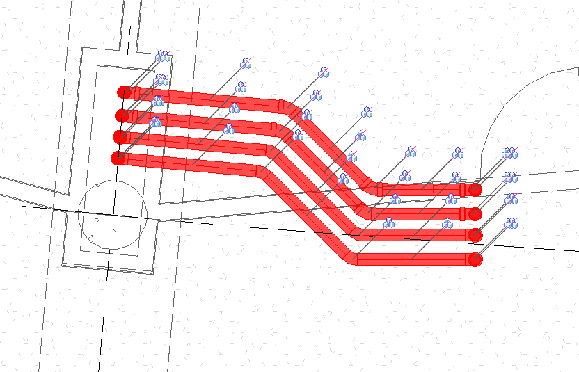
A problem that I have noticed cropping up with my fellow Revit users lately is that they can not select pipework bends with either a window or a crossing even though they are visible, yet they can select pipework.


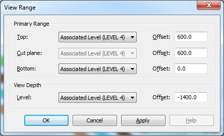
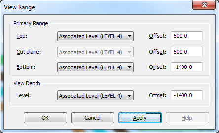
The solution is a simple fix, in the view range settings of the view, check that in the primary range, the bottom of your view range matches that of your view depth.

After the change has been applied, you will be able to select your pipe fittings as well as your pipes.

The initial setup

Unfortunately I have not had enough time to update lately due to work commitments, I haven’t even had time to approve comments to posts, so I feel that it’s time to make a worth while post and address one of the building blocks of a Revit project that I often see done incorrectly, the initial setup of the project itself.

Overview
When setting up an incoming model, the level of preparation will depend on two key factors

  • The relationship of the engineering team to the architectural team (shared project office or remote)
  • The size of the project. Large projects require additional consideration in regards to the impact on computer performance

In the instance where the engineering and architectural teams are co-located, it may be a consideration to directly link the architect’s live model into the engineering model. In this case, the architectural model would not be cleaned by the engineering team—request with the architectural team prior to project startup that ‘consultant views’ are provided for linking into the engineering model.

In the instance that the engineering and architectural teams are not co-located, it is the responsibility of the lead project modeller to clean the architectural model files before they are linked in. An original copy of the model should be kept in it’s ‘as sent’ state (located in \project number\in\date) so that if a mistake is made during the cleaning process, an untouched copy remains to safely start over with.

Large Models
For extremely large projects, consideration needs to be taken on the affects of computer performance, memory usage and overall performance of engineering models-particularly potential performance issues during the co-ordination phase.

Large models can be split physically into separate files, or split into separate worksets that can be unloaded as required to increase overall model performance. Discuss with the project architect their strategy. In most cases it is sufficient to unload unrequired architecture. If it is deemed necessary to split the engineering models, take into consideration how this may affect elements such as beams, columns, ductwork, cabling and pipework.

Preparing the Model
The basic level of cleaning consists of the following steps

  • Open the file
  • Check the ‘Detach from Central’ tick box
  • Click yes on the warning dialogue
  • Check the ‘Audit’ tick box

  • Open the ‘Manage Links’ dialogue
  • Remove all links that are not found
  • Change all attached links to overlays


  • Remove unrequired views
  • Delete all sheets, schedules, legends, drafting views and sections
  • Purge all unused elements


Setting up the Linked Model
The first step will be to start a new project using your organisation’s standard template relevant to your discipline.

  • Use transfer project standards to copy project information from the architectural file. This ensures that the information matches.
  • Link the architectural file using origin to origin
  • Acquire co-ordinates from the architectural model (outlined below)
  • Turn room bounding on for the architectural model
  • Pin the architectural so that it can not be moved.


Acquiring Shared Coordinates

After the link is inserted, from the manage tab, select Coordinates -> Acquire Coordinates

The status bar will update to say ‘Select a linked project from which to acquire shared co-ordinates’ – select the link you wish to acquire the co-ordinates from.

There is no prompt to indicate the co-ordinates have been acquired successfully. A quick way to check that it has worked is to try acquire the co-ordinates again—you will receive an error stating that the co-ordinates have already been synchronised.


 Model Location and Origin
The whole project team shall work on the models set up with identical locations and origina co-ordinates (as outlined on the previous page). It is essential that the location and the weather data are set correctly to enable energy analysis.

In Revit 2011 and later, Google Maps has been integrated within the location tool. This allows for the easy location of the project for correct energy analysis.


  • Type in the location to the search box, click search. Once found, this is now the project location.
  • Under the site tab, ensure your site is correctly named.

 Grids and Levels Setup
It is the architect’s responsibility to set up the grids and levels for the project.

Floor and ceiling plans will need to be created for each discipline. Use the copy/monitor tool to create levels and grids within the engineering model.


  • From the ribbon, select Collaborate -> Copy/Monitor -> Select Link
  • Select the link you will be copy/monitoring the grids and levels from
  • Select each grid and level to populate the engineering model

 
Creating Views and Plans

  • From the ribbon, select Views -> Plan Views -> Floor Plan
  • In the New Plan dialogue window, select the levels required from the list box. Verify the correct scale is used.


Enabling Worksets and Worksharing
Revit files contain everything related to the entire job, all the views, sheets, schedules, are all located within the one file. To allow more than one person to work on a Revit project at the same time, worksharing needs to be enabled. Until worksharing is enabled only one person will be able to work on the model at any one time.

Consideration needs to be taken when creating worksets. Plan ahead of time taking into account the size and complexity of the project and the number of services being documented within the model.


To enable worksets, select the worksets tool from the Collaborate tab on the ribbon

The worksharing dialogue will appear, informing you that it will break the model into two worksets; Shared Levels and Grids, and Workset1. Rename Workset1 to something that makes sense within your model. It is a good idea to relate it to the architecture, as all the models which have been linked so far will be moved to this workset.

The active workset shown in the collaborate tab of the ribbon is similar to the active layer within AutoCAD. Every object placed in the model will be placed in the active workset.

Saving to Central
The final step in the project setup is to save the file as a new central file. After enabling worksharing, by default the Revit file will automatically save as a new central file.

 Working on the Model
To work on the file, simply locate the saved central file and before opening, ensure that the ‘create new local file’ check box has been ticked. This will automatically create a new local file, using your computer username as a suffix, located in My Documents


Caleffi Revit Families

Need a specific valve for your Revit project and just can’t find it? I have a range of Caleffi valves including thermostatic mixing valves and balancing valves available for download, provided by Caleffi’s Australian distributor – All Valve Industries

A quick blurb about Caleffi from the All Valve website –

Caleffi valves have become synonymous with quality and value for money. Products include valves such as the pressure reducing valve, thermostatic mixing valve and backflow prevention devices and much more.


The families were not originally modelled in Revit however so modifications are limited or not possible at all, but for those wanting an accurate model of the valve to be installed, these families are for you.

Just an item to note, the valves have quite a high level of detail, be aware extensive use of the families in your model may slow down performance of your model.

Download here

[iframe: src=”http://freewheel.autodesk.com/dwf.aspx?path=http://www.revit.com.au/dwf/dcv-3D.dwfx&sec=1&px=13.308908&py=3.2166453&pz=-4.6169911&tx=7.8553017&ty=0.12048074&tz=-8.4556487&ux=-0.23353035&uy=0.89179190&uz=-0.38751875&fx=0.63681009&fy=1.1497906&proj=orth&q=high” frameborder=”0″ width=”100%” height=”400″ scrolling=”no”]

Basic Scheduling – A Real Beginner’s Guide

I have been queried a few times in the last week on the ability of Revit to schedule our hydraulic models, so I’ve quickly written up this short guide on how to make it work. It is really quite powerful and an easy process to undertake, provided you have modelled everything correctly, with less than 10 minutes of configuration, Revit can do instantly what it may have taken a few hours or even days to undertake manually.

Our hydraulic template is setup to schedule a few basic items out of the box, in fact to make this work, only a single additional parameter which we normally utilise for tagging was used to separate between each individual service. A good example of what can be quickly scheduled is pipe lengths. This is a quick run through on how to make scheduling work quickly. It can be applied to many other items as well.

I also decided to write this guide as simply as possible, the intention being that within our company, even non-Revit users would understand. The reason being is I often hear around the office “Oh but it’s so hard to make Revit do this…”

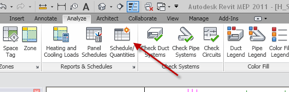
In Revit, under analyze, select schedules/quantities

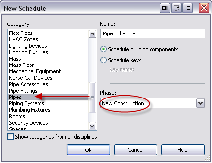
Select piping schedule and new construction

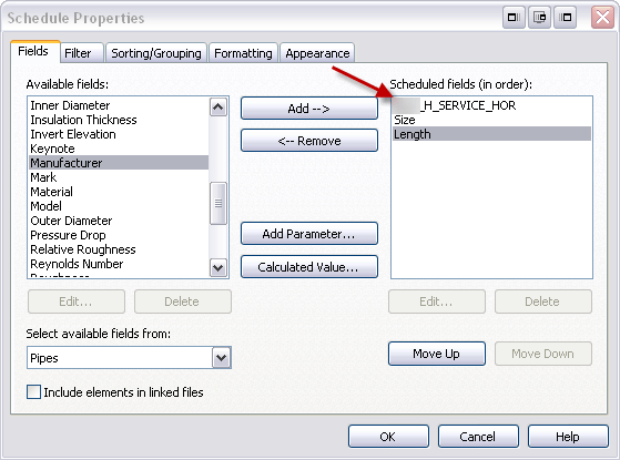
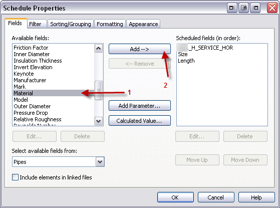
Add the parameters you want. In this instance, I used the H_SERVICE_HOR parameter as previously mentioned to filter by service. This way it will list the services in an easy to follow manner.

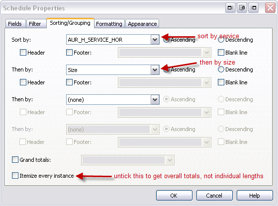
Select the sorting order as Service -> Size-> Length

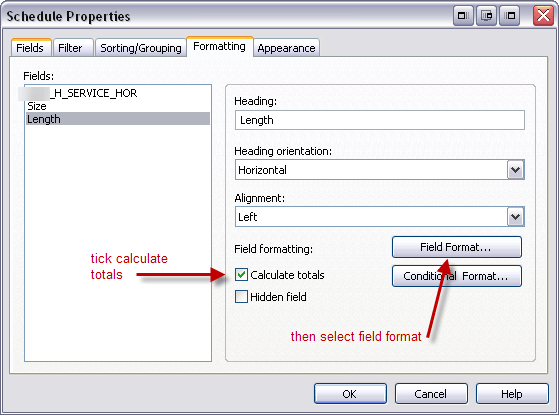
Format the fields as you want it to appear. The only one you should really have to change is length as the default measurement is in millimetres.

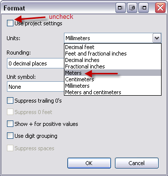
Change to metres.

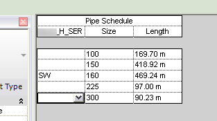
And admire the results. In this case the results did not appear correctly due to the pipework not being configured properly (whoever made this template needs a clip around the ears)

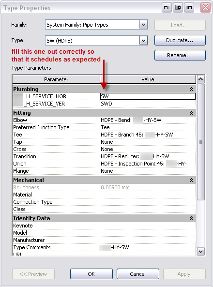
Don’t stress though, there is an easy way to fix this. Check the pipe settings within the project by selecting properties on the pipe type in the project browser.

The problem was that the H_SERVICE_HOR parameter was empty. Fill it out by using the drop-down box of template presets.

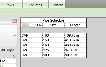
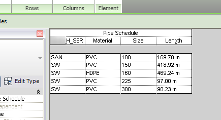
Now marvel at the updated schedule. But we used different materials.. no worries, we can modify the schedule to break down the results further.

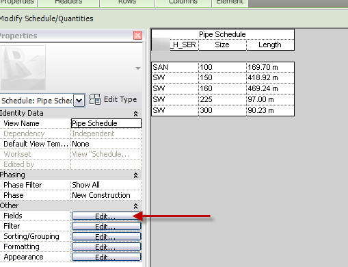
In the schedule properties, click the ‘Edit…’ button next to the ‘Fields’ parameter

Add the material to the list, use the ‘Move Up’ button to place the material parameter as the second on the list so that your hierarchy is now AUR_H_SERVICE_HOR -> Material -> Size -> Length

The finished results – now you can use in your pricing spreadsheet. Quantity counts that would have taken a day or more just took 10mins and now that it is setup, it will automatically update as you develop your model.

You can further apply this to create schedules on a per level basis by creating multiple schedules and splitting the schedule down further using additional parameters. For example, you can show how much pipework, plumbing fixture counts, sprinkler head counts or any other variety of configuration on each drawing for each service.

Free Revit Plugin – DPR Model Slicer

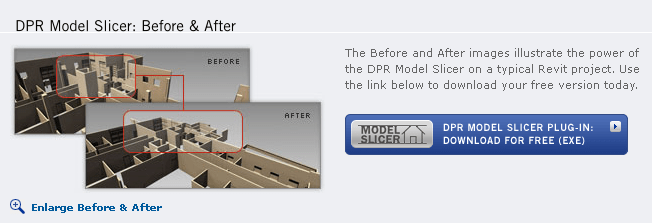
DPR Model Slicer has been around for a while now, I never really saw a whole lot of point in it as you can easily create 3D sections of levels by using the ‘orient to view’ option on your view cube or to filter by reference level.


The problem with the ‘orient to view’ method is time and filtering by reference level introduces problems with multi-floor elements such as walls or columns remaining visible for their full height which may not be the result you’re after.

The other day I was asked if there was a quick way to create a 3D section of every level at the same time with the same settings. I decided to give DPR Model Slicer a go.

It turned out to be able to do just that. Easy to install and intuitive to use, creating 3D sections for every level in a few seconds, I highly recommend it.

You can find DPR Model Slicer here – http://modelslicer.dpr.com/


Planning Families. Lessons Learnt as Families Develop.

In Australia we call it hydraulics. USA call it plumbing engineering. UK, health care engineering. Whatever it may be called in your region, you would be well aware that out of the box, content is severely lacking in Revit content.

I started using Revit MEP in 2008, Revit MEP 2009 was released the same week. The company I work for had won a project, a 7 storey plus basement, 5 star Greenstar rated office building built for the State Government. Myself and another drafter were sent off for some ‘intense’ two day training in Revit MEP so that we could learn the software to model this project. After 2 days we were supposed to be revit gurus.

Well. 3 years later and I still would not consider myself a Revit guru. A somewhat wise man once told me to never ever believe that you are the best at what you do. There is always bound to be someone out there better than you. Basically, it is a slightly self deprecating way of saying “you never stop learning”

Once we started modelling this project, with no prior experience other than our somewhat lacking education, we realised we had embarked on a long an arduous journey, this is where we come back to content.

For those that don’t know, the humble floor waste gully (FWG), or floor drain as some may know it, is a rather important piece of kit in hydraulics. In Australia, floor wastes are mandatory in some areas and optional in others. Generally you will see floor wastes in public bathrooms, where they are required beside urinals, or they may be collecting water from a nearby basin, shower or tundish. The concept is simple. Lets stick a grated drain in the floor in case anything floods, there is a way for the water to escape without damaging the building.

When I created my first floor waste family (based off the Iplex Palazzi style trap), I had no formal training in family creation, as such, there were no parametrics involved, the floor waste was simply a modeled based on my AutoCAD 3D experience and attached to a floor (floor based). This was my first lesson learnt.

In Revit, you can not host to walls, ceilings or floors in a linked model. Not immediately understanding what I had done wrong, I started to draw floors in the amenity blocks where floor waste gullies were required. I also had trouble creating a floor not bound by walls, so I had to create architectural walls as well. Quite a frustrating process, especially when rooms changed.

The other problem with this floor waste, I was convinced, was lack of parametrics. Because I didn’t even know where to begin, with no help to be found, no Revit site I could find had any useful information on creating parametric families, I had to live with a fixed position family.

I chose an arbitrary height of 300mm from the top of slab. This was great for some areas, not for others. 500mm thick slab. No worries, floor waste can sit in the slab. I have to admit, even though the family looked great, it also looked somewhat unprofessional.

The next development in my floor waste family was to change it so that it was hosted to a face, rather than a floor. Already a great improvement over the last. Problems were still apparent though. At the same time that we are still developing our Revit capabilities, so are many architects. Many people will tell you, especially people from a Revit MEP background, that deleting walls, floors and ceilings from your Revit Architecture model is a big no no! Rather you should move them where possible. The reason behind this is that any objects hosted to your now deleted elements, like FWG v2.0, will cause dramas for the MEP modeller.

Thanks to some formal training in family creation, I though I would solve my fixed position floor waste problem once and for all. As you can see, this new and improved version had an integrated riser which is attached to a face, which when inserted in the MEP model would be the floor. Brilliant! Well it just wasn’t meant to be. On the next project, were were dealing with an inexperienced architect, floors were being deleted left right and centre, even after we very clearly communicated with them to stop deleting things and to move them instead.

Most of the time this resulted in the either the floor waste family being completely deleted, or to cause headaches with pipework connections downstream.

The other issue was the integrated riser. If you needed to change the height of the floor waste to cater for a thicker slab, or to make an easier connect to a drain, you had to change a parameter, which is fantastic until you change it too far and all the pipework disconnects.

So in essence I had created a brand spanking new revision of the family which essentially had all the same problems, just for different reasons. Second lesson learnt.

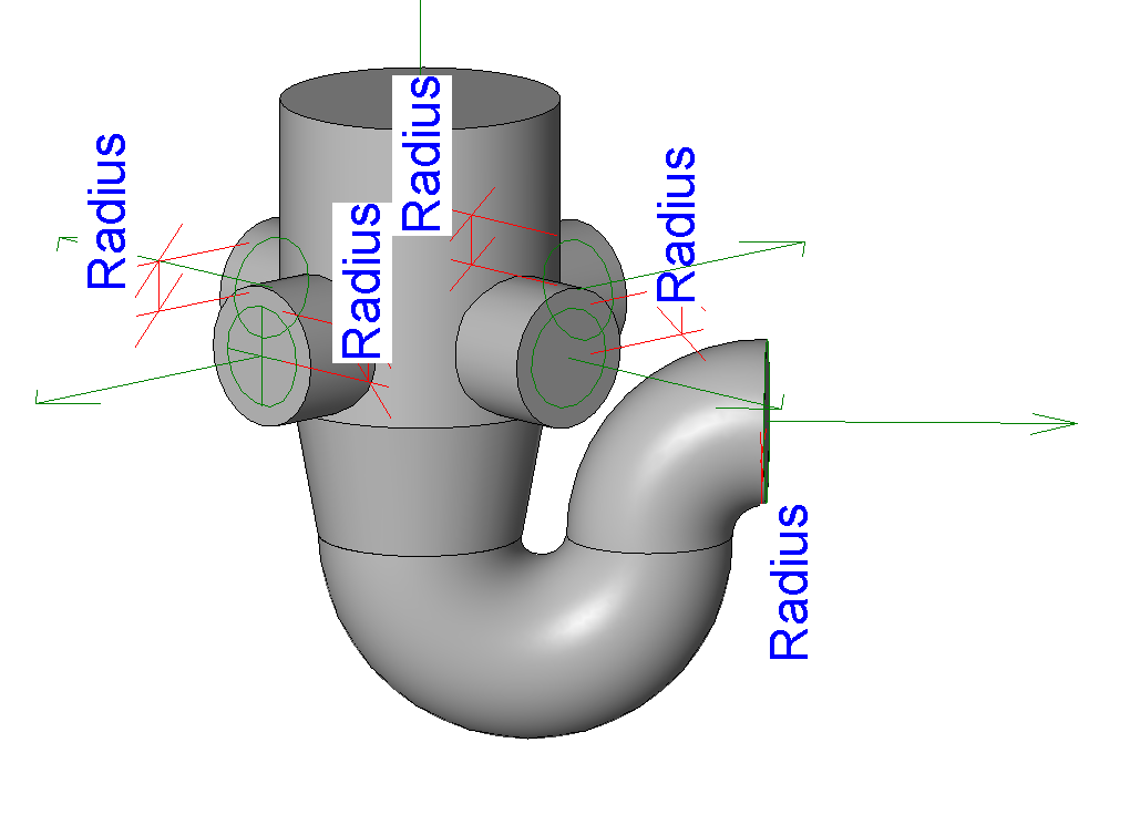
The next, and at this point final revision which we will call FWG v3.0, has what I think are two great leaps forward in development. The first, and probably the most important, is that the family is no longer hosted to anything. Floating around with no host association was the solution to the majority of our problems.

The floor waste now has a pipe connection at the top of the four-way riser. The idea is that you draw a pipe vertical from the family to the floor or reference level. You can lock the top of the pipe to the floor or reference level if you wish. As long as you do not try to raise the level of the FWG above the slab, you no longer have troubles with pipework disconnecting when the height is changed.

Not content with simply fixing the riser issue, I decided to make some changes to the four way riser which was actually the request of one of our modellers. Previously, the four-way riser was fixed, only allowing connections in 45 degree increments to the outlet. With a lot of hair pulling and the odd desire to throw my computer out the window, I finally figured it out. We now have a rotating four-way riser.

I spent what is no doubt too many hours trying to get the riser to rotate properly. The reason why I was failing was because I was trying to rotate multiple extrustions which I had attempted to lock together with reference planes and fixed dimensions. Lesson 3 learnt.

The secret to making it work is quite simple. I re-created the four-way riser as a seperate family. Once the riser section was nested into the trap family, I was able to apply an angular parameter, linking it to a reference plane within the nested riser family.

Now that I have somewhat perfect floor waste family, I have created a few more based on the same concept. In Queensland, we more often use 100 dia floor waste rather than the 80×65 floor waste I has originally modelled. But there is still a requirement for both.

I have now applied my lessons learnt from my original 80×65 FWG to the 100 dia FWG, shower traps, clear outs, overflow relief gullies and many other core hydraulics components that do not come with Revit out of the box.

Revit 2012 File Upgrader

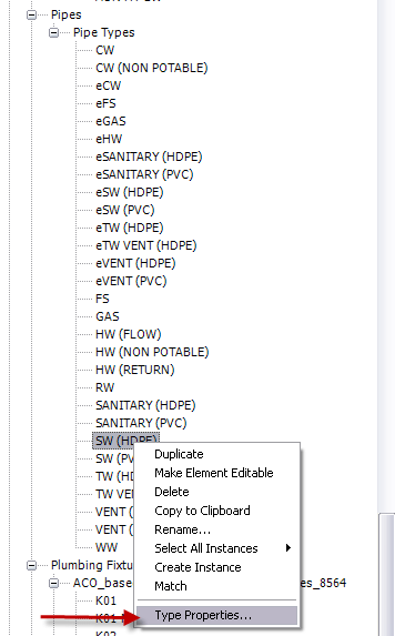
Autodesk have released a batch file upgrader for Revit 2012. The program is intended to upgrade family content from previous versions of Revit to 2012.
You can find it here:
http://labs.blogs.com/its_alive_in_the_lab/2011/06/file-upgrader-for-revit-june-adn-plugin-of-the-month-now-available.html

Direct link:
http://labs-download.autodesk.com/us/labs/files/FileUpgrader.zip