Ryan Lenihan

Conditional AND / NOT / OR Statements to Control Visibility Within a Family

I get a lot of wish lists at work. The latest one was how to show both ordinary hazard and light hazard sprinkler coverage within a sprinkler family, but also have the option to not show it at all. The intention is to allow quick initial layouts or spot checks of coverage in accordance with Australian Standards without having to maintain separate views with separate view templates.

To be honest, I’m not convinced of the validity of this method over simply turning off the visibility of subcategories in Visibility/Graphics, but it was a nice chance for a quick “Well sure I can do that!” There is nothing stopping the end user from overriding the display of the subcategories either.

In the below image, within the same family we have the coverage for ordinary hazard, light hazard and no coverage displayed, controlled by 2 tick boxes.

20-06-2013 11-28-57 AM


20-06-2013 11-33-48 AM

So how do we achieve this?

With a fairly simple combined AND / NOT statement within the Revit family.

I have used 4 instance parameters to achieve the above results. These parameters are ShowOrdinaryHazard, ShowLightHazard, DisplayCoverage and OrdinaryHazard.

The two parameters ShowOrdinaryHazard and ShowLightHazard are driven by DisplayCoverage and OrdinaryHazard and are the only parameters the end user is able to change.

The formulas used are

ShowOrdinaryHazard = and(OrdinaryHazard, DisplayCoverage)

Which only ticks ShowOrdinaryHazard if both OrdinaryHazard and DisplayCoverage are checked.

ShowLightHazard = and(not(ShowOrdinaryHazard), (DisplayCoverage))

Which only ticks ShowLightHazard if DisplayCoverage is checked but ShowOrdinaryHazard is not checked.

20-06-2013 11-41-27 AMOf course, as mentioned in the 2nd paragraph, I’m not convinced of the validity of this method, at least for this implementation. Subcategories and view templates are all you really need. Why complicate things just because you can?


Long Radius Bend Conduits Are Not Long Radius in Coarse or Medium Views

I had a question from one of our modellers in NZ this week about long radius bend conduits not appearing correctly in coarse or medium mode, but they appear correctly in fine mode.

As you can see in the two screenshots below, the conduits on the left are in fine mode, and the 3D representation of the conduit accurately shows the long radius bend. The conduits on the right are the same conduits displayed in coarse mode, however the long radius bend is not reflected at all.

20-06-2013 9-51-32 AM 20-06-2013 9-51-43 AM


It is a relatively simple solution, but it is something that is easily overlooked as the option is tucked away under Electrical Settings.

From the Manage tab on the ribbon, under the Settings pane, select MEP Settings -> Electrical Settings.

20-06-2013 9-52-15 AM


In the list on the left hand side, select Conduit Settings, then in the right hand side of the window, un-check Use Annot. Scale for Single Line Fittings

20-06-2013 9-52-34 AM


Unfortunately, this will not apply to previously drawn conduit, it will only apply to newly drawn conduit. If you want long radius conduit to appear correctly in coarse or medium mode you will need to redraw it.

It is worth noting that there are similar options that apply to cable trays, duct and pipe. The options for duct and pipe are found under MEP Settings -> Mechanical Settings

Automatically Close Those Pesky IFC Import Warnings

Lately I have been dealing with IFC files on a regular basis. Quite large IFC files in fact. On average these files are taking 90mins to import into Revit.

On smaller projects, it isn’t too much of a problem to manually act on the warning dialogue boxes that pop up when elements unjoin or openings can not be created. These files though, I like to import them overnight with a few open instances of Revit so they’re ready for me in the morning.

Alas, those pesky warning dialogue boxes weren’t helping me out at all, coming into work in the morning with buttons to click and more time to wait.

There is a solution though, using scripts created in AutoIT, I no longer need to wait. Simply start the scripts and leave them running, start the IFC import and away you go. The AutoIT scripts will automatically close the dialogue boxes after a 5 seconds.

If you’re having the same problems on large IFC imports, you can download the scripts below.

AutoIT Scripts for MEP 2013

AutoIT Scripts for One Box 2013

Some virus scanners may falsely identify these files as malicious.

Quickly Annotating Vertical Elements in a Model

Have you ever had a large floor plan, covering multiple floor and have literally hundreds of risers to tag? What if all the risers are offset through the building and you can’t simply copy and paste the annotations up the building?

Tag all is a great solution for which I have a little tip on how to speed the process up and it’s quite a simple solution as well.

First step, open the floor plan you want to tag and cut a section that covers the whole building. For the purpose of this example, I’m only going to use a small riser section that I’ve mocked up.

17-04-2013 12-09-40 PM


In the section view, I find that it is easier to turn off all the architecture. Select all the pipework that relates to the level you want to tag. I just select a crossing and filter everything out leaving only pipes selected.

17-04-2013 12-10-49 PM


Switch back to the floor plan view. Make sure that the markers showing the pipes are selected are visible in the floor plan otherwise this will not work. If you have dependent views, make sure you are in the top level view that shows the entire floor plan.

17-04-2013 12-10-58 PM


Now using the tag all tool, select the relevant annotation tag, set your preferences for leader on/off and leader length, click OK and you’re done.

17-04-2013 12-11-28 PM


Of course, at first everything comes up a little untidy, but it is far quicker to align annotation symbols that to tag each vertical element manually and then locate the annotation.

17-04-2013 12-13-48 PM

Another step that you could take if say you had a hydraulic project and you wanted to tag all the drainage stacks with a dropper annotation symbol and then tag the vents with a riser annotation symbol is to simply filter out each service through visibility graphics in the section as you go, annotate the vertical elements in a few steps rather than all in one hit with the same annotation symbol.

17-04-2013 12-35-02 PM


Hydraulically this solution is far more advantageous for drainage services than it is for water services, as drainage always drops and vents always rise, where as water can go either way, but it still goes a long way toward cutting down your annotation time on a project.

The Positives and Pitfalls of Automating 0A, P1 etc. Revisions in Titleblock

A commonly asked question is can we have a 0A or P1 revision in our titleblocks in Revit. Most of the time, the answer is ‘No’

There is a solution however that can at least help us with the revision schedule in the titleblock, unfortunately the solution doesn’t work outside of the revision schedule itself.

The first solution below is to prefix revisions 1 – 9 with a 0, resulting in 01, 02, 03 etc.

In your titleblock family, edit the revision schedule, add the parameter ‘Revision Sequence’ and create a calculated parameter named ‘_Revision Number’

01_createparameters

The calculated value needs to include the following formula, or some variation of the formula

if(Revision Sequence = 1, “01”, if(Revision Sequence = 2, “02”, if(Revision Sequence = 3, “03”, if(Revision Sequence = 4, “04”, if(Revision Sequence = 5, “05”, if(Revision Sequence = 6, “06”, if(Revision Sequence = 7, “07”, if(Revision Sequence = 8, “08”, if(Revision Sequence = 9, “09”, ” “)))))))))

02_calcvalue


The calculated value needs to be a text value for this to work.

What the formula does is create a new revision number based on our newly created _Revision field. If the revision sequence is 1, then the value substituted (which will be shown in our title block) will be 01. You can do this for all sorts of variations such as P1, CD1, 0A and so forth.


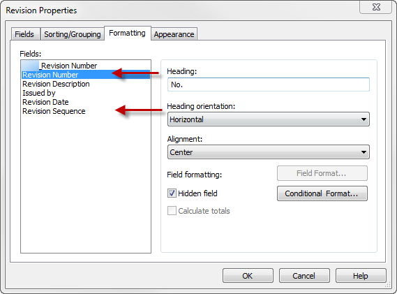
Next, under the formatting tab, hide the fields ‘Revision Number’ and ‘Revision Sequence’ so that these values do not appear in our schedule.

03_hidevalues

Adjust the schedule to suit the revision columns in your title block. The next step is to add another schedule to achieve an automated revision number at the bottom right of the title sheet. To do this we need to create a second revision schedule.

Revit restricts you to only having one revision schedule in the titleblock family by default, however there is a work around to this. Open a second titleblock family, name the revision schedule something else and then copy and paste it into the titleblock you’re working on. You need to select the visual representation of the revision schedule in the sheet and use CTRL+C and CTRL+V to copy the schedule from one title block to another.

04_newschedule    05_pastedschedule

Now repeat the steps above to create the calculated ‘_Revision’ parameter within the second schedule. This time around there is an additional step, under the appearance tab, select ‘Build from bottom up’ and change the height to user defined so that you can limit the number of revisions shown to one. You need to adjust the height of the revision schedule visually in the sheet rather than in the revision properties dialogue box.

06_2ndschedule

Place the second schedule aligned to the bottom corner of the titleblock as required to appear correctly. The revisions of the titleblock are now automated to whatever you like.

The problem with this solution though is that to work, it needs to be driven by the default ‘Revision Sequence’ parameter within Revit. Of course, this doesn’t directly relate to your revision. If you have a look at your revision dialogue box, the first column is the revision sequence. Revision sequence 3 could actually relate to Revision 03 on the project, but it could also relate to revision 02 on another sheet, or 01 on yet another. Therefore, even though we have a nice sequence of IF statements to generate revisions 01 – 09, by the time we actually get to revision 09, which might actually be at revision sequence 14.

15-04-2013 10-00-22 AM


The second solution will overcome this problem and is probably a little cleaner if say for example you wanted to place a P in front of all revisions for a preliminary series of issues, it could be anything from revision P1 through to P999.

Create another schedule within the titleblock, which I have named mine ‘Self Populating Schedule Prefix’ which sits alongside the main revision schedule so that it appears as a single ’01’ or ‘P1’ or whatever the revision might be. This would mean that you need 4 schedules in total within the titleblock family – remember you need to copy and paste them from another titleblock to have more than one.

08_newsolution


I have then removed the ‘_revision’ calcualted value from the main schedule and replaced it with the regular revision number, which in this case will be 1, 2, 3 etc.

In the new ‘Self Populating Schedule Prefix’ schedule, I have recreated the ‘_revision’ calcualted value, this time with the following formula

if(Revision Sequence > 0, “P”, ” “)

Which simply creates a prefix of P if there are any revisions at all, if there are no revisions, then it will be blank.

When inserted into the project, the revisions will appear automatically with the P prefix, no need for dumb text to be inserted which eliminates error when you’re rushed to get documents out.

09_revision1 010_revision2


But what if you no longer wanted to prefix your revisions after a certain point? Easy. Say we moved to Tender at revision sequence 23, we would simply change the calculated value’s formula to

if(Revision Sequence < 24, “P”,” “)

Which would prefix all revisions with the letter P up until sequence 23. What if beyond sequence 23 we wanted to prefix our revisions with T as well? Again, a pretty simple formula

if(Revision Sequence < 24, “P”,if(Revision Sequence > 23, “T”, ” “))

Of course this will only make sense if you change from numerical revisions to alphabetic revisions when you move from preliminary to tender.

So clearly there are limitations, unfortunately not all work arounds are perfect, but if you can achieve what you want within these limitations, it is a huge help in eliminating human error when you’re rushed to issue documents.

Using Ideate BIM Link and areas in Revit MEP for quick and easy calculation models

22-03-2013 5-03-01 PM

I was handed a dirty big piece of paper the other day by a Revit capable engineer with lines that were traced in AutoCAD, complete with manual calculations and tables calculating the catchment areas for a large project that we’re working on currently. I was asked to take the sheet of paper, a calculator and “get to it” to provide the total flow that would be discharged to two separate civil catchment areas. I was a bit taken aback to be honest.


I took it upon myself to create a calculation model that would automate the process. Not only does the model produce a higher quality output, but the model can be used throughout the life of the project, updated as changes filter through from the architects and adapted and manipulated for other rainfall calculations across the project.

BIM/IPD [Aus]

I took some time out last night to attend the Australian Institute of Architects/Consult Australia launch of the BIM in Practice documents. For the last 2 years they have been putting together some reference material to assist the industry. They’re documents to make you think, documents to get your started to to steer you and your company on the right track.

From the webiste:

The material is the first output from four cross-disciplinary working groups under the direction of the BIM & IPD Steering Group established by the Australian Institute of Architects and Consult Australia. Groups of highly respected built environment industry professionals have built on previous efforts to develop guidance and resources for practitioners who work using BIM and who aspire to implement IPD on their projects.

Last night’s event launched those documents and a new website, BIM/IPD Australia, as well as acknowledging the work of the individuals and companies involved in the working groups which produced those reference documents.

The documents deal with and give guidance on –

BIM Management Plans
BIM Legal and Procurement
BIM Education
BIM Outreach

Automatically Inserting Symbols Into Revit Schedules

Just a small sneak peak of something that I’ve been working on recently. Revit users everywhere would know that the one short fall of Revit scheduling is that you can not include annotative symbols within the schedule.

Schedules are very powerful and are normally used to generate fixture counts, lighting schedules, pipework counts and the humble drawing legend. If only Revit would insert the symbols though.

I’ve been working on an alternative approach to the problem which is working great so far! I’ve created a short video with my progress. No audio or anything fancy, just showing that the concept works.

I recommend viewing the video in full screen at either ‘original’ or ‘1080p’ display settings.

httpv://www.youtube.com/watch?v=sQsD9JSf4Ak

Making Revit Work For You Using Advanced Families.

Lately I have found that a lot of the buzz about Revit is 3rd party add-ins and software. Sure they’re great and save a lot of time in our workflow, but what about making Revit itself do some work for you?

Earlier this week I created a box gutter sump family that replaces an Excel spreadsheet that I used to use.

You simply input the data you would normally enter into a roof drainage calculation sheet into the Revit family, I also added a few more inputs to allow further control over the family. The inputs are

  • Catchment area
  • Rainfall intensity
  • Minimum box gutter depth
  • Minimum sump depth
  • Maximum sump depth

From there, all the calculations are built into shared parameters. I decided to use the KG Martin method for sizing (from the CSIRO Experimental Building Notes 1978). Hydraulic designers sizing roof drainage know all too well about h, 2h, Dg and Dmax which were easy to work into the family in a step by step process.

My original effort at creating this family I had devised excessively complicated formulas in an attempt to reduce parameters and what I originally thought to be simplifying the family as a whole. If I had taken advice from my Planning Families post though, I would have started out a little differently. When working through a family, you not only have to take into consideration the 3D elements, but parameters as well. What resulted in an excellent parametric family had absolutely nothing that I could schedule out.

With all the calculations undertaken step by step within shared parameters, I have 17 results I can include within a Revit schedule. The outputs from the family now include data such as:

  • Catchment flow rate
  • Calculated maximum flow rate achievable by sump/outlet combination
  • Depth of sump
  • h (depth of gutter flow at discharge end)
  • Dmax (depth of gutter flow at still end)
  • Dg (Dmax + freeboard)
  • Gutter high and low points
  • Td (total gutter depth)

The schedule includes conditional formatting to warn that either the outlet is too small or the sump too shallow/excessively deep. As a further step, I also included a visual warning in the family itself, displaying a text box indicating the error within plan view.


The schedule can then be added to a calculation sheet within the project for design verification purposes.

The data inputs for each sump/outlet can be controlled through the schedule, or the user can double click on the sump within the schedule which will then take them to the family within the project.

The next step is pipe sizing. You would probably know already that Revit does not include a sizing method that specifically applies to stormwater drainage, however I have had some success using the hydronic supply system type with accurate results up to 100l/s which of course uses the data calculated within the family.

For me, being a hydraulic designer and Revit modeller, this family eliminates some double handling in data entry, saving time in modelling and performing calculations. Data entry time is further reduced by creating a fixture tag that pulls the gutter size and sump size from the shared parameters with the family. All for a lazy 90mins development time.