I’m often asked about hardware recommendations by friends and colleagues. I thought I’d collate my thoughts which you can find here


I’m often asked about hardware recommendations by friends and colleagues. I thought I’d collate my thoughts which you can find here

You may have noticed that when modelling pipework on grade, displaying that grade as a percentage, Revit rounds a grade of 1:60 (1.65%) to 1.67%

This is due to 1 / 60 being 1.66 recurring, which Revit correctly rounds to 1.67. Regardless of if Revit is correct or not, hydraulic engineers, project verifiers and council inspectors will argue that the 0.02% difference is incorrect. Why? The Australian Standard of course. The table in Appendix B of AS/NZS3500.2 shows that 1:60 = 1.65% and this is what people want to see on documents.
Usually the first step you instinctively take is to try and re-apply the slope to your pipework, but 9 times out of 10, Revit doesn’t want to do this.
Don’t fret, the solution is an easy one. Head to Project Units which you can find under the Manage tab on the ribbon.
In the Project Units dialogue box, select Piping from the drop down, then click on the button to the right of Slope

By default, rounding is set to 2 decimal places. Change this to custom, then type in your preferred rounding increment which in this case is 0.05

Click OK until you’re out of the Project Units dialogue box and looking back at your project. Notice that all your annotations have updated?
If you select your pipe, you will see that even though your annotation says 1.65% your pipe is actually still sloping at 1.66 recurring.


A common question I receive at work is “How do I turn off these pesky light sources in Navisworks?”
The answer? Quite easily.
First, select one of your lighting fixtures, from the selection tree, expand out the lighting fixture element, finding the light source itself.

Once you have selected the light source, if you check the properties window, you will see that the material of the light source is named “Default Light Source”

If you check a few more lighting fixtures, you will see that this is the same for all of your lighting fixtures, so all you need to do is create a simple selection set and turn the light sources off.
To create a selection set, go to the find items window, and then input Material -> Name -> = -> Default Light Source as per the screenshot below. Once you have done this, select Find All

Then it’s as simple as clicking hide

Before:

After:


Have you ever had problems locating 3D families correctly and having 2D annotations of that family clash with each other? This is a quick guide on how to make those 2D annotation symbols within your family moveable with grips.
In this example I am starting with an empty family. Keep track of where your Front/Back and Right/Left reference planes are as we will be using these to assist us with creating the moveable annotation symbol.First, create 4 new reference planes, 2 horizontal and 2 vertical as per the image to the left.

Note that I’ve highlighted the reference planes that I have added in red for clarity.

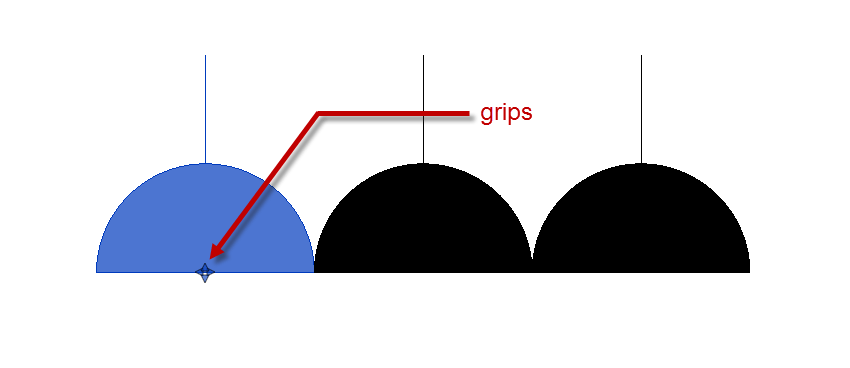
Select the outer reference planes that you have created and set them to Not a Reference.Select the inner reference planes that you created and set them to Strong Reference.Setting the inner reference planes to strong references will give you grips / shape handlers to be able to move your annotation symbol about the page.
Setting the outer reference planes to not be references will mean there are no grips at all and you will not accidentally move your 3D component.

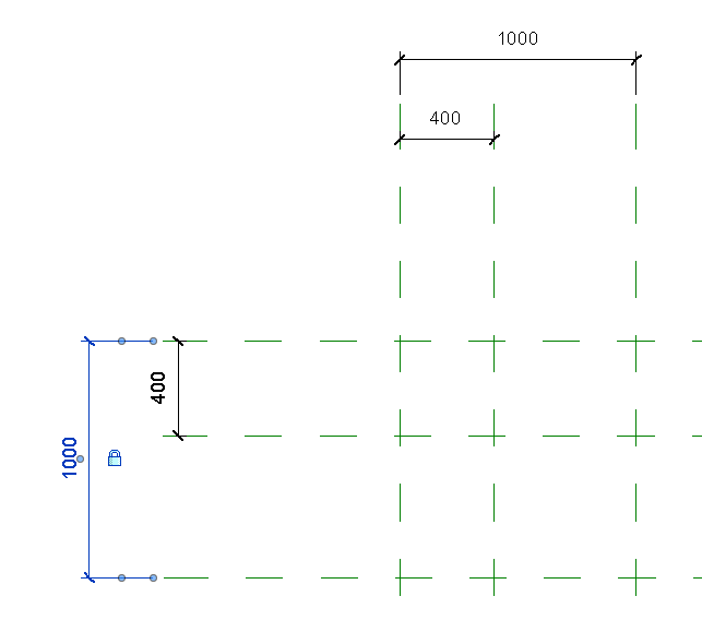 Set the outer reference planes to 1000mm (1m), dimension them with aligned dimensions and lock them.
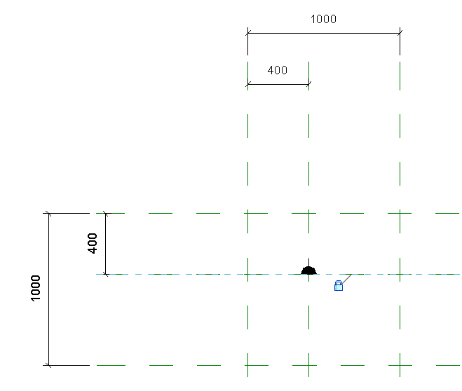
Add dimensions from the outer (locked) reference planes, to the inner reference planes. Your screen should look something like the image to the left.
Select these dimensions and add Horizontal_Offset and Vertical_Offset parameters to the horizontal and vertical dimensions. Note that these parameters need to be instance parameters.
Insert your annotation symbol if you haven’t already, for the example, I am using a GPO symbol. Align and lock your annotation symbol to the inner (highlighted) reference planes so that the annotation symbol is located centrally (or offset if required) to these reference planes. Note that you should have drawn your annotation symbol centred on the reference planes, this will allow you to align and lock to these planes.

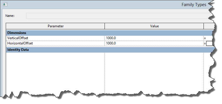
Finally, in Family Types change the Horizontal_Offset and Vertical_Offset parameters to 1000 to centre the annotation symbol correctly within the family.
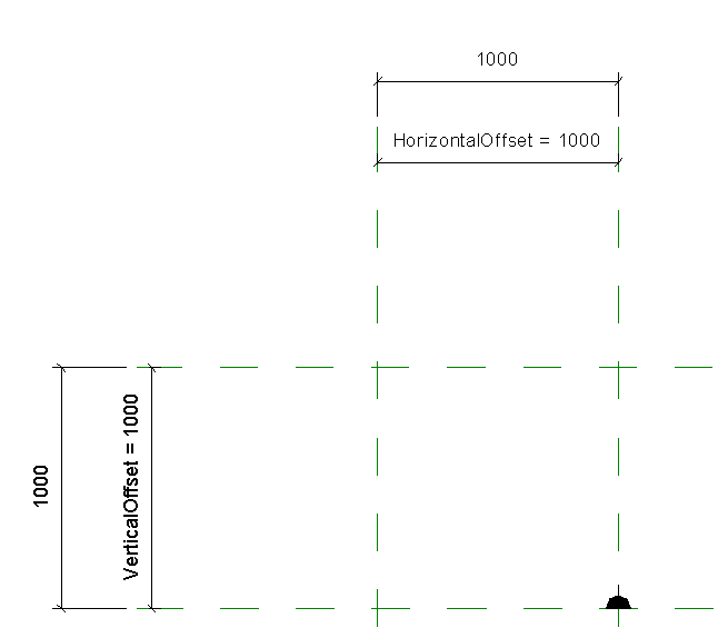
When you place the family into a project, you will notice that you now have grips to move the annotation symbol away from the 3D element, without moving the 3D element itself.

A few people have asked me how I quickly deleted the views in my previous post. The answer is quite simple. Filters. I needed to keep two pre-defined views in the RVT files that I was issuing to the client.
First up, right click on Views at the top of the Project Browser and select Browser Organisation and create a browser organisation settings. In this example I am using Revit 2014, if you are using an earlier version of Revit what you see will be slightly different to my screenshots.

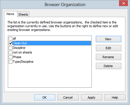
The two views that I wanted to keep are named $Navisworks Export and Start Page, so in the Filters tab of Browser Organisation Properties window we need to filter the browser to show results that are not $Navisworks Export and not Start Page as per the screenshot below. Unfortunately contains is not an option, so we can only choose a view name with an exact match.
We then need to simply group by none on the Grouping and Sorting tab.


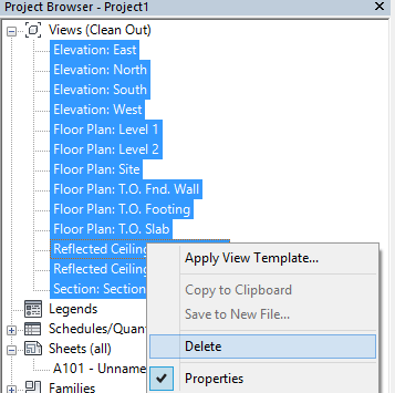
The result is a list of all the views that we want to remove. Simply select all and delete them. You can select all your views (floor plans, ceiling plans, 3D views, drafting views etc), legends and schedules and delete these all at once. If you want to delete the sheets, you will need to select and delete them seperately.

For those of you that have access to the Autodesk Subscription centre, there is a little tool tucked away in the list of downloads called eTransmit for Revit.
eTransmit? Surely not! That is an AutoCAD thing right? Wrong.
This tool will allow you to:
I had to issue 25 models today, in both RVT and IFC formats. The RVT files needed to be purged, audited and have all the views except 2 stripped out. A daunting task just due to the amount of mind numbing clicking and waiting needed to get to the end result.
You can find eTransmit under the Add-ins tab of the ribbon once it is installed.

 Then just simply adjust a few settings and away you go. If you want to purge the files, make sure to check the radio button asking Open and save models in the active version of Revit and then obviously tick the check box Purge all unused. eTransmit won’t actually generate any views, so it’s quite quick.
The results, I purged an electrical services model from 87mb to 31mb in 3 minutes.
All 25 models complete in under an hour.
Oh, and the best part? When you open the file you see this little dialogue box. The file will not be re-created as a central until you choose it to be. There is absolutely no risk of someone accidentally opening the file in your outgoing files folder and syncing back the changes.


The secret to parametric families are reference planes. Of course, you can apply parameters that adjust the dimensions of elements without the use of reference planes, but some things just won’t work that way.
One of those things is filled regions. A good example of this is an electrical distribution board symbol. Distribution board symbols are always shown dimensionally accurate (Revit detail item), unlike a GPO for example which would always appear the same size on a sheet of paper regardless of the scale (Revit annotation symbol). It’s easy enough to adjust the outer box of the symbol as you can apply parametric dimensions directly to the lines, but what about triangular filled region?
Start with you detail item family template, add the reference planes to control the overall dimensions of the symbol.

Then draw in the outer edge of the symbol, locking the lines to the reference planes

Next, draw in the filled region, making sure that the end point of each line snaps to an endpoint or an intersection of a reference plane. The locking of the end point to the reference plane is automatic.


When you’re finished, your symbol should look something like this

And when you change the Length and Width parameters, the filled regions will automatically adjust along with the rest of the symbol.

Make sure these parameters are instance parameters, load the symbol into your distribution board family and then link the instance parameters in the symbol to the related parameters within your distribution board family.

Now you have a symbol that scales correctly with the 3D components of your family.

The question came up at work yesterday about if it were possible to draw pipes in Revit at angles of less than 5°.
With a bit of tweaking, it is possible, but personally I would be wary that you would be modelling something that isn’t actually constructable as fittings at less than 5° are not available in the real world.
So what is the tweaking you ask? Check out the video below
Although bends of less than 5° are not a real world fittings, this may be an acceptable solution in a situation where say a corridor has slight bends in it (oh architects!), or you have to reticulate pipework around a curved football stadium; on-site a contractor may be installing plastic pipe that has a little flex in it and will be able to achieve that slight bend that you just can’t model in Revit.

I have had the situation recently where I was working remotely over the VPN on a data link that left a lot to be desired. Unfortunately my area isn’t serviced that well by ADSL and the NBN is years away.
Opening and saving back to a central file of about 50mb wasn’t too much trouble, but opening the 400mb of links was a massive problem. I needed a solution so I could work on my files and fast.
What I ended up doing was using the subst command in DOS to generate a pseudo network drive on my local system and replicated the folder structure below that. The central file and all of the associated links were saved at their UNC path \\work-network\projects\job number\revit
I opened the central without it’s links and then repathed the links to their windows path z:\job number\revit
The result being that I could access and save to the same central file as the modellers back in the office and no one was affected by linked models being pathed to the wrong place because on their next save to central / reload latest, the paths of the links were updated to z:\job number\revit, everything worked seamlessly.
Of course, a few times I forgot to subst the drive before loading the central file which obviously resulted in links not loading, so to solve this problem I put together some code in c# which performed the drive subst for me and then set the program to run on startup.
The code is quite basic, really only a single line
using System;
using System.Collections.Generic;
using System.Linq;
using System.Text;
using System.ComponentModel;
using System.Runtime.InteropServices;

namespace CreateVirtualDrive
{
 class Program
 {
 static void Main(string[] args)
 {
 System.Diagnostics.Process.Start("cmd.exe", "/c subst z: d:\\work");
 }
 }
}
Just keep in mind that this is only generating the drive letter, not the directory structure, so you need to ensure that the directory structure between the pseudo drive and the server match exactly otherwise it will not work.
It’s not a perfect solution, but it works well with minimal effect to everyday workflow. It does exactly as intended, eliminating the wait time loading large chunks of data across a slow VPN link. The linked models only need to be copied across the VPN when updated rather than on each open.

We discovered an interesting problem on this particular project where the tag all feature would not work. Luckily, there is a simple work around.